


22 Installation
UM5C05C P0745680 Standard 6.00 October 2001 Emerson Energy Systems
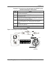
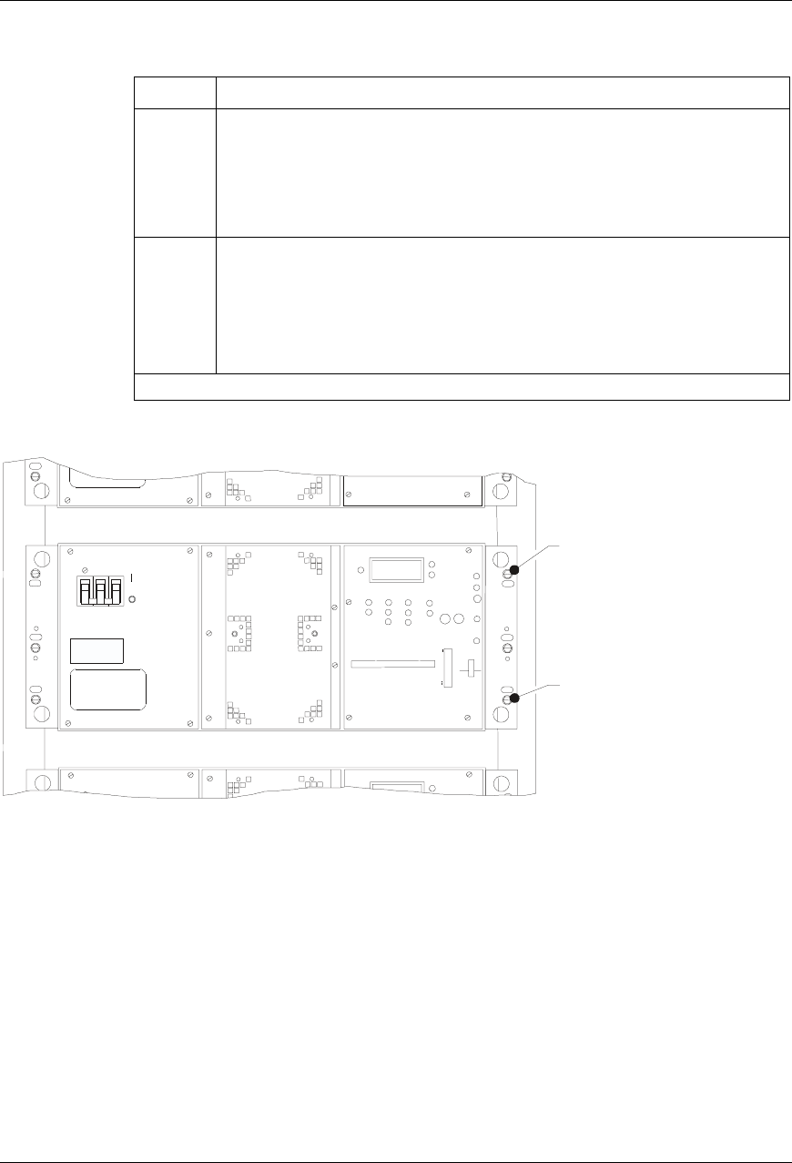
Procedure 2 - Installing a rectifier in a cabinet ( continued )
Step Action
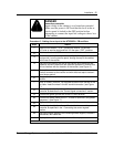
4
Place the rectifier on the L-shaped guides located in the lowest
position of the cabinet and slide it towards the rear until the mounting
brackets come into contact with the frame of the cabinet. The front of
the rectifier should be flush with the front of the cabinet and the
output bussing should be in contact with the riser busbars located at
the rear of the cabinet.
5
Align the mounting holes in the brackets of the rectifier with the
mounting holes in the frame. Secure the rectifier in place by inserting
and tightening the self-tapping screws removed in Step 3.
Note : Install an external tooth lock washer on one of the screws to
assure good ground continuity between the rectifier and the
frame.
end
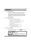
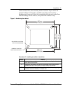
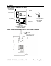
Figure 4 - Installing the rectifier
HELIOS
AC/CA
VOLT
AMP
VOLT/AMP
VOLT
CAL
CUR
CAL
CL
ADJ
EQL
ADJ
EQL
FLT
THSD
HVSD
RFA
FAN
ALM
VOUT+
SEN
FAIL
EQL
VOUT-
AC ON
CL
FF1
1.0A
FF2
1.0A
FLT
ADJ
HVSD
ADJ
STU P
DLY
SLS FS
DC/CC
HELIOS
VOLT
CAL
ET LOCK WASHER
SELF-TAPPING SCREW
( P097F813 )
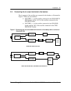
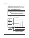
3.4. Cabling and connecting
The ac cables of the rectifier must always exit each rectifier from the right
side, when viewed from the rear.
The dc cables of the rectifier must always exit each rectifier from the left
side, when viewed from the rear.
The system alarm interface cable must always exit each rectifier from the
right side, when viewed from the front.