


Operation 47
Emerson Energy Systems Rectifier 200I/48NT5C05C Installation and User Manual
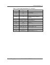
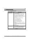
Procedure 9 - Starting up the rectifier ( continued )
Step Action
Adjusting the float voltage
14
Ensure that the EQL / FLT switch is on the FLT position.
15
To adjust the float voltage to the proper level, turn the FLT
potentiometer clockwise to increase the voltage or counterclockwise
to decrease it.
Adjusting the equalize voltage ( EQL )
16
Set the EQL / FLT switch to EQL. Turn the EQL potentiometer
clockwise to increase the voltage or counterclockwise to decrease it.
17
Put the FLOAT / EQL switch in the FLOAT position.
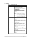
Adjusting the slope share
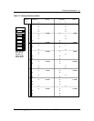
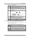
18
Select the slope share mode
by setting the two bottom DIP switches
to SLS ( see Figure 10 ). Verify that the rectifier displays the required
float value. If required, adjust it with the FLT potentiometer.
19
Connect the sense leads by inserting the RC fuse in the controller or
by reconnecting the control cable.
20
Put the dc breaker located on the front of the rectifier to ON.
21
The rectifier is now connected to the system and should carry some
current. If it is connected in parallel with other rectifiers, verify that
the total system current is shared equally amongst the rectifiers. Put
the switch on each rectifier to AMP. Find the mean current of the
rectifiers by adding all the currents measured on each rectifier and
dividing the total current by the number of rectifiers
I
T
= I
1
+ 1
2
+I
3
… + I
n
n n
Set the current from each rectifier to this mean value. If the current
reading of one of the rectifiers is too low, or is 0, slowly increase the
current by turning the FLT potentiometer clockwise until proper
sharing is achieved. If the current reading is too high or if rectifier is
in the current limit mode, turn the FLT potentiometer
counterclockwise.
Note : Adjust all the rectifiers in sequence to the mean value of the
currents, and readjust more precisely if necessary.
Verifying the current limit
22
Turn OFF some of the other rectifiers to force the rectifier under test
to pick up a load current of at least 210 A. When the rectifier reaches
about 205 A, the yellow CL LED should light up.
continued