


50 Maintenance
UM5C05C P0745680 Standard 6.00 October 2001 Emerson Energy Systems
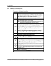
CAUTION
Preventing short circuits
The replacement operation is safe, as only SELV
circuitry is present behind the fan assembly. However,
due to the possible presence of residual charges in the
output circuit, do not use metal tools within the rectifier
enclosure. To remove the fan assembly mounting screws
you need a screwdriver, but all the other operations
described below can and should be performed without
any tools.
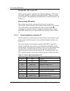
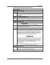
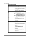
Procedure 10 - Replacing the fan unit
Step Action
Disassembling
1
Put the ac and dc breakers to OFF.
2
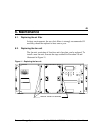
Remove the five screws securing the fan plate ( see Figure 11 ).
3
Swing open the assembly and disconnect all four fan cables.
4
Lift the assembly out the holes and pull it out towards you.
Re-assembling
5
Insert the hinged bracket of the new assembly into the slotted holes
on the left and reconnect the cables to the four fans.
6
Place the four fan cables close to the display panel, removing as
much slack length as possible, so the cables will not interfere with
the fan blades after the fan unit is secured in place.
7
Swing the fan unit closed and secure it in plate with the five screws.
8
Check fan fuses FF1 and FF2 and replace as required.
9
Put the ac and dc breakers to ON.
end
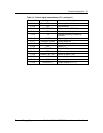
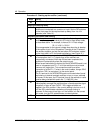
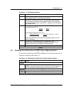
6.3. Calibrating the Volt / Amp Multimeter
In a cabinet or frame application, where the signal cables are connected to
the NT6C43PB board, use a digital multimeter, at J13 on the NT6C43PB
board, to monitor the shunt reading of the rectifier, as indicated in Table 9.
In any applications where the NT6C43PB board is absent or has been
bypassed, pins P1-19 and P1-7 of the signal connector provide the shunt
reading. To access pins P1-19 and P1-7 use a cut P0747000 cable. If the
meter must be calibrated execute the steps in Procedure 11.