


Functional description 33
Emerson Energy Systems Rectifier 200I/48NT5C05C Installation and User Manual
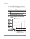
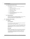
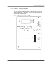
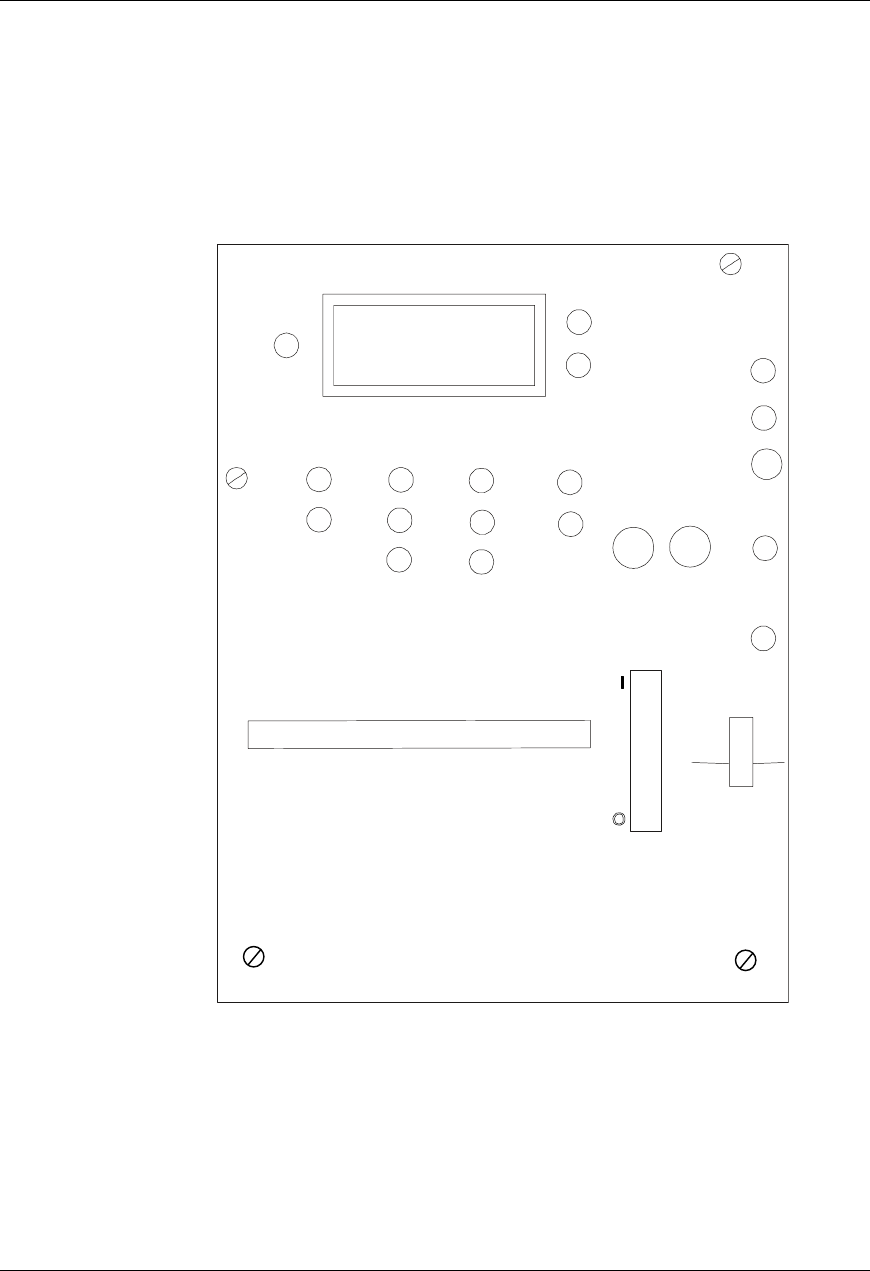
4.2.2. Switches, controls and LEDs
There are switches and potentiometers on the front panel to adjust the
operating parameters of the rectifier. The LED indicators indicate the
operating and alarm conditions.
Figure 10 - Front panel controls and LEDs
FF2
1.0A
FLT
FF1
1.0A
CL
A
C ON
VOUT-
EQL
SEN
FAIL
VOUT+
FAN
ALM
RFA
THSD
EQL
EQL
ADJ
CL
ADJ
CUR
CAL
VOLT
CAL
HVSD
VOLT/AMP
A
MP
VOLT
HVSD
ADJ
FLT
ADJ
ST UP
DLY
SLS
FS
DC/CC