


UPS Interconnection Kits
91
Appendix A.3.2 Status/Control Connections - Liebert Npower UPS Interconnection Kit
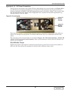
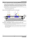
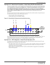
The status/control interface is the Liebert Npower Battery Information Board (BIB). The connection
of the BIB is described in Figure 140 - Control wiring diagram—Liebert FS - optional electri-
cally operated circuit breaker Liebert Npower units. Refer to this drawing to ensure that the
proper connections are performed. In case multiple Liebert FS units are connected to the same UPS
DC bus, refer to Figure 132 - Control wiring diagram, Liebert FS power rack system in paral-
lel for capacity to perform the Status/Control connections between each Liebert FS.
This interconnection kit includes Status/Control Connections that enable transfer of signals between
the Liebert FS system(s) and the UPS system such as:
• Circuit breaker status (closed/open); and
• Undervoltage relay coil excitation voltage.
The recommended gauge for status/control connection wires is 16 AWG - 600VDC (1.3mm
2
wire sec-
tion). Wire size and installation must comply with all applicable local, regional and national regula-
tions (e.g., National Electric Code for USA).
Appendix A.3.3 UPS Configuration - Liebert FS and Liebert Npower
To optimize the integration between the Liebert Npower UPS system and the Liebert FS, some
parameters must be checked on the UPS system:
• The UPS rectifier walk-in time must be set at a value as low as possible. Contact your Liebert rep-
resentative if your unit has received the upgraded board that permits the setting of “rectifier
walk-in time” lower than standard.
• Ensure that the “auto battery self test” has either been disabled or upgraded to accommodate
Liebert FS integration.
Appendix A.3.4 Liebert FS Configuration - Single Liebert FS Unit
The following Software Control Parameters must be set when the Liebert FS is connected to the
DC bus of the Liebert Npower UPS system.
NOTE
The Software Control Parameter values specified below are recommended. These values may
require adjustments due to the battery type. These must be used unless otherwise specified by
the Liebert-certified service technician at initial system startup. Instructions to set these
parameters on the Liebert FS are in 6.5.3 - Control Parameters Setup at Initial System
Startup.
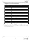
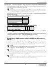
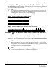
Table 23 Liebert FS Software Control Parameters
Liebert FS Software
Control Parameter
Setting
Charge Voltage 530VDC
Regulation Voltage 520VDC
Vreg Delta 0VDC
Maximum Charge Current See Table 24
Charge Amps/Volts See Table 24
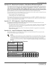
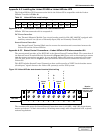
Table 24 Liebert FS Software Control Parameters varying with UPS size
UPS Output Rating (kVA) 30 40 50 65 80 100 130
Liebert FS Maximum Charge Current (A) 11 15 19 25 31 38 50
Liebert FS Charge Amps/Volts (A/V) 0.8 1.0 1.3 1.7 2.1 2.6 3.4
DISCONTINUED
PRODUCT