


Installation
24
4.1.2 Wood Floor Mounting
Determine which of these cases applies to your installation:
• For wood flooring over concrete, follow the instructions in 4.1.1 - Concrete, Masonry or Stone
Floor Mounting.
• For wood flooring on joists, follow the instructions in this section.
Wood Floor Mounting Parts
• Two (2) cabinet mounting brackets (previously secured Liebert FS cabinet to shipping pallet)
• Four (4) (1/2" diameter x 2-1/2" long) [or 12.7mm diameter x 63.5mm] lag screws (not included in
mounting kit) are recommended
• One floor mounting template, see Figure 149
• Four (4) 1/2" diameter x 3/4" long (12.7mm diameter x 20mm long) hex bolts (from shipping pack-
age—see 3.2.2 - Unpacking)
Wood Floor Mounting Tools
The following tools are needed for the cabinet wood floor mounting:
• Electric drill
• 1/4" (7mm) drill bit
• Drill bit—used for pilot hole—for example, 1/8" (3.2mm) diameter
• Shop vacuum cleaner (to remove dust from hole when drilling)
• 3/4" (19mm) combination wrench
• 18mm combination wrench
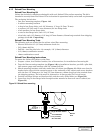
Wood Floor Mounting Instructions
Installation in wood floor on joists does not require drop-in anchors.
1. Prepare a clean, level surface, free of obstructions, for installation of the mounting kit.
2. Tape the floor mounting template (Figure 149) to the installation location.
3. Drill pilot holes, remove the template and use a 1/4" (7mm) drill bit to drill holes 2.5" (64mm)
deep.
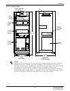
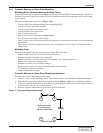
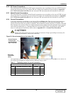
4. Match mounting brackets with holes under base of cabinet (see Figure 21). Make sure that the
bracket holes align with the mounting spots on the underside of the cabinet and secure brackets
with the four hex bolts retained from the shipping package. Each bolt is 1/2" diameter x 3/4" long
(12.7mm diameter x 20mm long). Tighten the bolts with a torque wrench at 40 foot-pounds
(54 N-m).
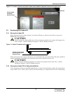
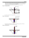
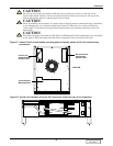
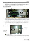
5. Insert two lag screws through bracket mounted at rear of cabinet leaving head with 1/2" (12.7mm)
gap above floor (see Figure 22).
6. Position and align cabinet and bracket slots with the newly drilled holes at rear and position
cabinet such that bolts fit in bracket slots (see Figure 22).
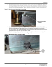
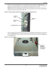
7. Insert two (2) lag screws through bracket mounted at front of cabinet (see Figure 23).
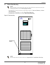
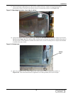
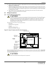
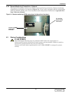
8. Check the bubble level on the floor of the cabinet on the right hand side of the Power Conversion
Module (see Figure 24). The Liebert FS is sufficiently level when the bubble is within the outer of
the two circles. If the bubble is outside the outer circle, use the leveling feet to adjust until bubble
is within the outer circle.
9. Once the cabinet is level, firmly tighten the front lag screws to a torque 40 foot-pounds (54 N-m).
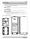
!
CAUTION
Ensure that holes are centered in the joist.
DISCONTINUED
PRODUCT