


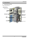
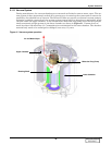
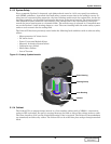

System Overview
36
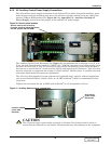
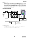
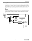
5.1.6 Power Conversion Module
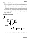
Power Conversion Module Controller (PCMC)
The Power Conversion Module Controller is located within the Power Conversion Module. The PCMC
uses microprocessor-controlled logic to control the six pulse IGBT solid state switches and monitor the
active magnetic levitation system.
These operations are firmware controlled eliminating the need for manual adjustments. The logic
includes a self-test and diagnostic circuitry to identify any faults. Diagnostics are performed via a PC
through the RS232 communication port or through the control panel located on the front of the Lie-
bert FS.
IGBT Power Conversion Module (PCM)
The PCMC provides the overall control of the Liebert FS as well as the specific control for the syn-
chronous reluctance motor generator via the IGBT solid-state switches within the Power Conversion
Module.
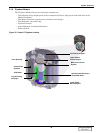
The Power Conversion Module is a bi-directional system capable of sourcing or sinking power to and
from the stator. It converts variable frequency, variable voltage from the stator and delivers a con-
stant voltage DC output. Conversely, it converts DC power from the UPS System DC Bus to variable
frequency, variable voltage output to the stator as directed by the PCMC to increase the speed of the
synchronous reluctance motor-generator.
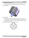
When delivering DC power, the output of the synchronous reluctance generator is rectified to DC by
passing the high frequency AC current through a solid-state power conversion device. The DC output
voltage of the Liebert FS has less than 2% Vrms ripple.
The voltage and frequency are adjusted using Pulse Width Modulation. The IGBT switches operate at
a frequency of 18 kHz to produce the smooth sinusoidal current waveform to and from the motor gen-
erator. This is smoothed out further using an inductive and capacitive filter.
DISCONTINUED
PRODUCT