


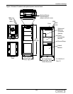
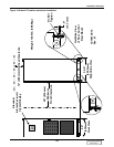
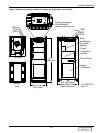
Installation Drawings
132
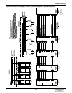
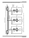
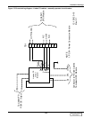
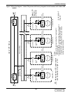
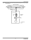
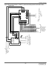
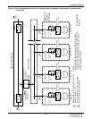
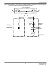
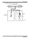
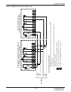
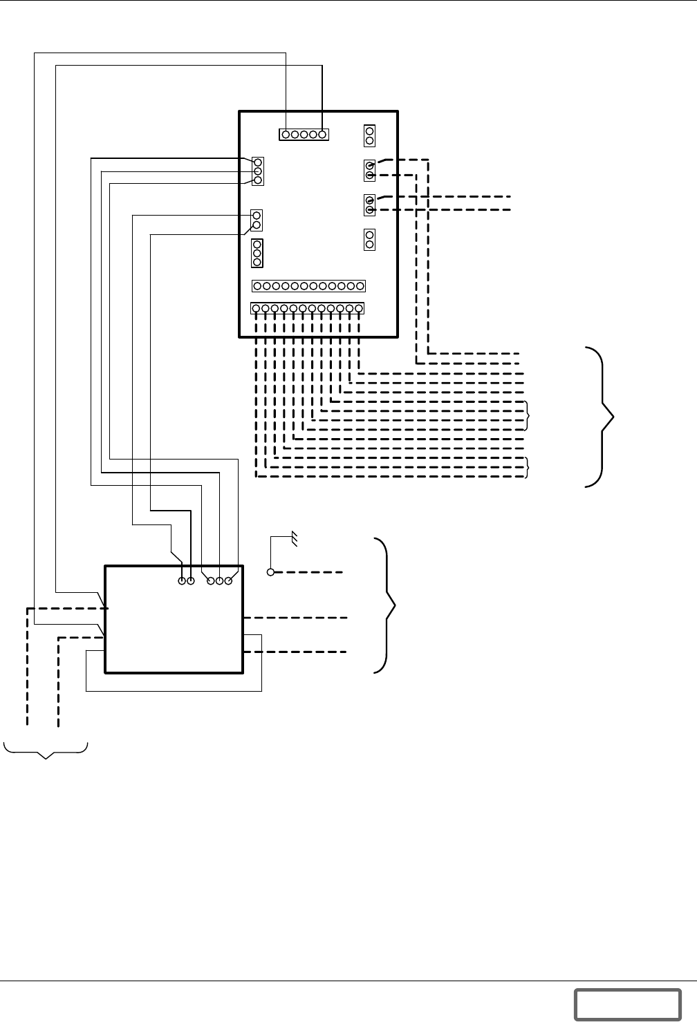
Figure 140Control wiring diagram—Liebert FS - optional electrically operated circuit breaker Liebert
Npower units
T B3
TB1
TB2
TB5 TB9
P2
TB8
400
401
113 Therm (In)
114 (Therm (Out)
Contractor to Provide Cables
to Liebert UPS Module
Yellow
Blue/Yellow
Blue
Brown
Brown
(-)
(-)
(+)
(+) (GND)
(-)
(+)
400
401
Liebert FS
Circuit Breaker
To Liebert FS
PCM DC
Output
Motor Oper. Power
Yellow N .C.
Blue/Yellow
Blue N.C.
Brown
Brown
12-100120-19
Rev. 0
Note:
1. PCM – Power Conversion Module
101 24 VDC +
102 24 VDC -
103 Control Relay Power
104 Motor Oper . On Signal
105 Motor Oper . Off Signal
106 N.O.
109 Logic GND
113 Therm (In)
114 Therm (Out)
112 (-)
110 (+)
108 N.C.
107 Common
TB4 TB6 TB7
Contractor to
Provide
Cables to
Liebert UPS
Module
Breaker Aux.
Contacts
UVR
Control
Aux.
Contacts
UVR
DISCONTINUED
PRODUCT