


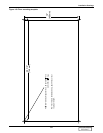
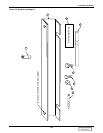
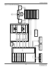
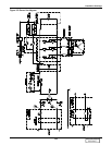

Installation Drawings
137
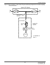
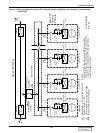
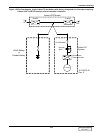
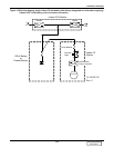
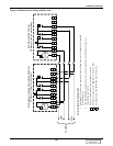
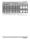
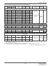
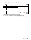
Figure 145 Wiring specifications, Liebert FS and Liebert Series 300
Wire
No.
Terminal Designation
Signal
Name
Maximum
Voltage
Maximum
Current Color
Wire Size
& Type
Maximum
Length RemarksFrom To
Series 300 UPS - Cable Group # 27 (Flywheel CB IFM) From I1 In UPS Module to TB1 on Liebert FS Module
901 I1-TB1-1 TB1-1 Trip Signal (+) +24 VDC 100mA
1/C #16
(2.5 mm
2
)
Stranded
500 ft
(150 m)
902 I1-TB1-2 TB1-2 Trip Signal (-) -24 VDC 100mA
903 I1-TB1-7 TB1-7 Aux Comm 24 VDC 100mA
904 I1-TB1-8 TB1-8 Aux N.O. 24 VDC 100mA
Series 300 UPS - Cable Group # 116 Flywheel Aux Power, Customer-Provided to Liebert FS TB1 on Fused Disconnect
914 FBO TB1-1 Line 120VAC 3.5A
1/C #16
(2.5 mm
2
)
Stranded
500 Ft
(150
Meters)
UPS-
Protected
Auxiliary
Control
Power
915 FBO TB1-2 Neutral 120VAC 3.5A
916 FBO TB1-3 GND 120VAC 3.5A
1. Each cable group must be run in a separate, grounded, rigid metal conduit to prevent control signal interference.
2. Refer to UPS module/Liebert FS control connection diagram for location of wiring connections.
3. All external wires furnished by others.
4. N.O. = Normally Open; N.C. = Normally Closed; Comm = Common; F.B.O. = Furnished By Others, GND = Ground
5. All wiring must be in accordance with national and local electrical codes.
Dwg. No. Control_WL_S300_Liebert-FS Rev. 01
DISCONTINUED
PRODUCT