


Installation Drawings
145
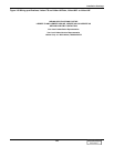
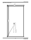
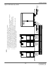
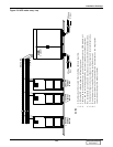
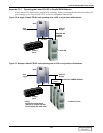
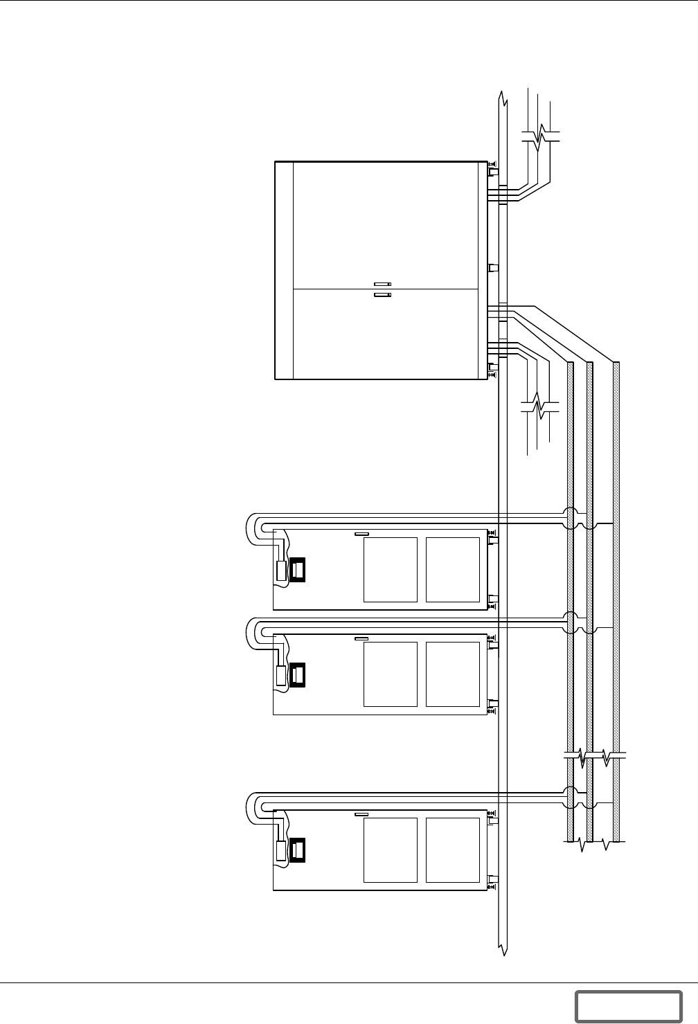
Figure 153 UPS cable entry—bottom
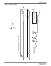
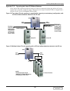
( + ) Bus
(-) Bus
Ground Bus
Liebert FS
Cabinet
Un it N
Liebert FS
Cabinet
Unit N
Liebert FS
Cabin et
Unit N
3-Phase
Output
UPS
CABINET
3-Phase
Input
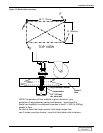
NOTES
1. All cables should be routed before bolting cabinets together.
2. All Liebert FS cabinets shown with front door open.
3. Cabinets shown connected as one system. When connected to a UPS module, all power
and control wiring supplied by customer (standard) or Liebert (option).
4. See installation, operation and maintenance manual for additional information.
5. All external wiring is to be in accordance with national and local electrical codes.
6. Bus wiring must be capable of handling total load current.
7. Power connection must be connected with a bus structure or to a single point
connection at the UPS (Do not daisy-chain).
DISCONTINUED
PRODUCT