


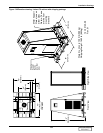
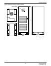
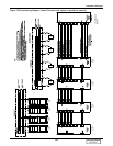
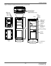
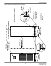
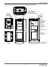
Installation Drawings
129
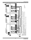
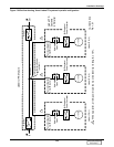
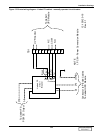
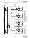
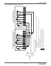
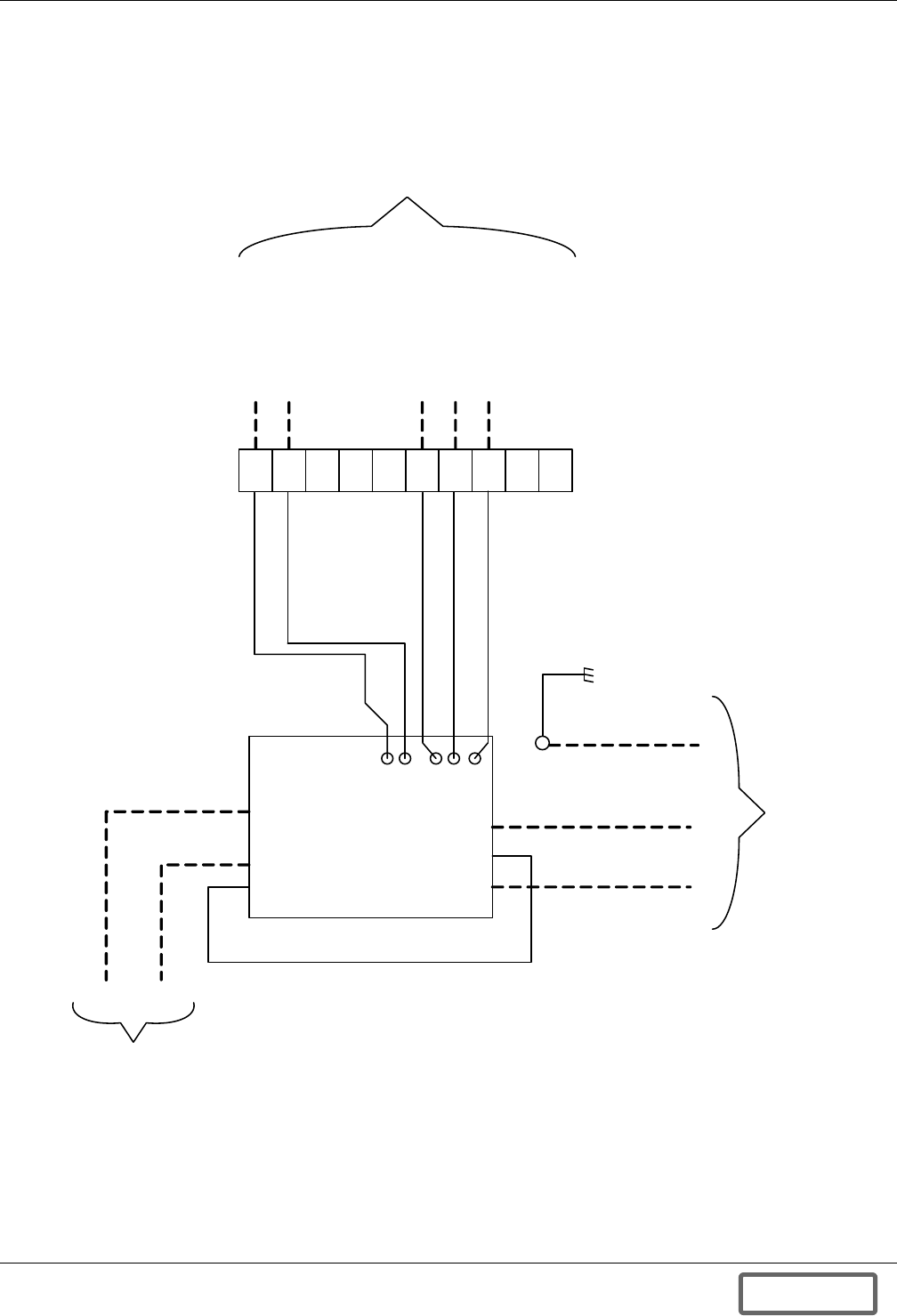
Figure 137Control wiring diagram—Liebert FS cabinet - manually operated circuit breaker
1
3
3
4
5
6
7
8
9
10
(+)
(-)
(+)(-) (GND)
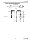
To Liebert FS
PCM DC Output
NOTE
1. PCM – Power Conversion Module
TB1
UVR Control
NC
NO
COM
To Liebert
UPS Module
12-100120-16
Rev. 01
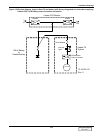
UVR
Aux.
Contacts
Liebert FS
Circuit
Breaker
Blu
Brown
Brown
Blu/Yel
Yel
Contractor to Provide Cables
To Liebert UPS Module
DISCONTINUED
PRODUCT