


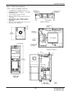
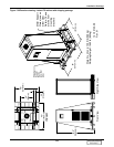
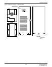
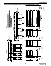
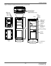
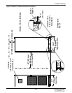
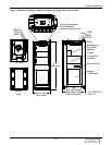
Installation Drawings
121
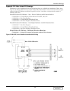
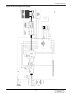
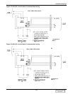
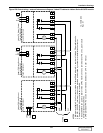
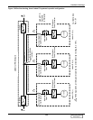
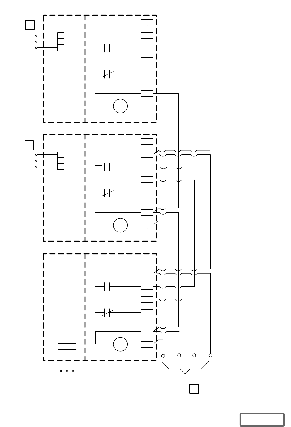
Figure 129 Control wiring—external interconnect diagram, Liebert FS cabinet to Liebert Series 610 UPS module
10
10
1 2 3
9
9
Fused Disconnect
Liebert FS Status/Control
Terminal Block #3
Line
N
3
Gnd
10
10
9
9
Fused Disconnect
Liebert FS Status/Control
Terminal Block #2
3
1 2 3
Line
N
Gnd
TB1
10
10
9
9
6
6
Fused Disconnect
Liebert FS Status/Control
Terminal Block #1
Line
3
Gnd
N
TB1
1
2
3
UVR
1
1
2
2
8
8
6
6
7
7
1
1
2
2
UVR
TB1
6
6
8
8
7
7
NOTES
1. Minimum available UV coil current must be N times 50mA where N = number of Liebert FS paralleled units.
2. 16AWG - 600VDC (minimum) wires to be provided and installed by customer or installation contractor.
3. Contact closed when circuit breaker is closed.
4. Series 600/610 can power a total of three UVRs maximum in any combination of FS units, plus module
battery disconnect switches.
5. UPS-protected 1PH AC source recommended. See Section 2.4.4 in user manual.
12-100120-04
Rev. 01
Aux
UVR
To UPS
1
1
2
2
UVR
8
8
7
7
5
4
5
5
DISCONTINUED
PRODUCT