


Installation
26
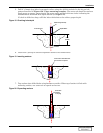
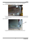
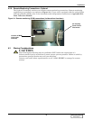
6. Attach a large diameter washer, a lock washer and a nut to each hex flange bolts as described in
Figure 25 and Figure 155.
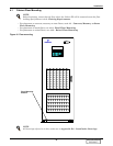
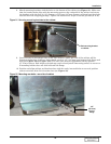
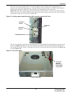
7. Check the bubble level on the floor of the cabinet on the right hand side of the Power Conversion
Module (see Figure 24). The Liebert FS is sufficiently level when the bubble is within the outer of
the two circles. If the bubble is outside the outer circle, use the leveling feet to adjust until bubble
is within the outer circle.
8. Once cabinet is level, firmly tighten down all hex flange bolts with nuts. The bolts must be
tightened to 40 foot-pounds (54 N-m) of torque.
4.2 Wiring Connections
4.2.1 General Wiring Considerations
The electrical connections to the Liebert FS are:
• DC power
• Status/control (upgraded)
• Ground
• Auxiliary backup power
• Remote monitoring—optional
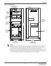
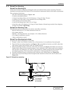
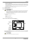
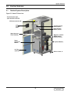
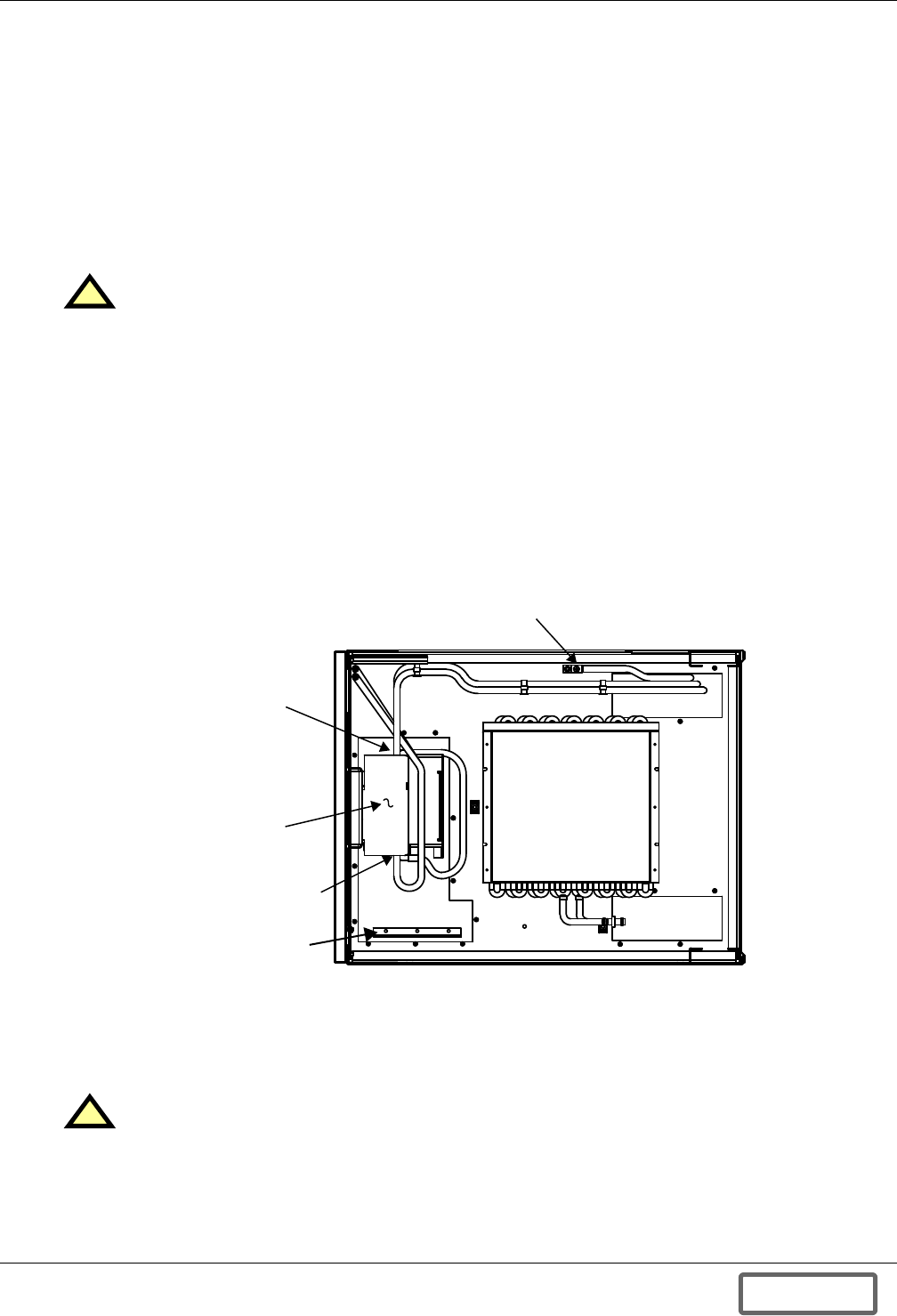
Figure 26 Liebert FS cabinet with UPS interconnection kit
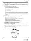
Power and Status/Control wiring must be run in separate conduits or cable trays. Refer to Appendix
D.0 - Installation Drawings for locations of the various electrical connections between Liebert FS
system(s) and UPS system.
!
CAUTION
A qualified electrical contractor must perform all electrical connections. The wires (DC power,
ground, upgraded status/control and auxiliary power supply) that connect the Liebert FS
system(s) to the UPS system are field-supplied or by Liebert as an option. Wire size and
installation must comply with all applicable local, regional and national regulations (e.g.,
National Electric Code for USA).
!
CAUTION
Power and Status/Control wiring must be separated.
DC Power
Terminals
Front
Rear
Circuit
Breaker
Status/Control
Terminal Block
(upgraded)
Manufacturer’s
Connection
Fan Coil Module
Ground Terminal
DISCONTINUED
PRODUCT