


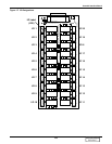
Versatile Interface Board
110
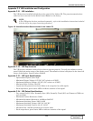
Appendix C.2 VIB Installation and Configuration
Appendix C.2.1 VIB Installation
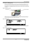
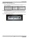
The VIB has been installed behind the service panel of the Liebert FS. The power/communications
cable has been connected to the Main Control Module at the factory.
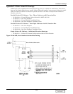
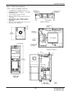
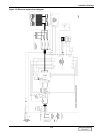
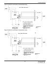
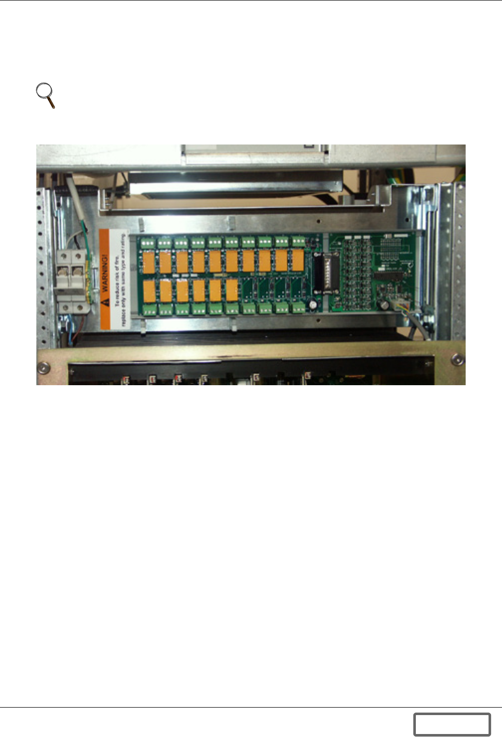
Figure 118 Versatile Interface Board mounted in the Liebert FS
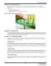
Appendix C.2.2 VIB Requirements
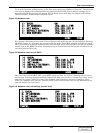
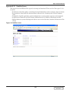
The VIB requires software version 2.09 or later to operate properly. To verify the software version,
press F6 from the main screen of the display panel. The software version is displayed in the lower left
corner of the display. Press F6 when finished.
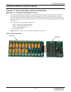
Appendix C.2.3 VIB Input Specifications
• Opto-isolated inputs, active high.
• Minimum Trigger Voltage: 3.5V DC (“IN” relative to “COM”).
• Maximum Operating Voltage: 32V DC (“IN” relative to “COM”).
• Minimum Input Current: 5mA DC.
• Inputs must be present for at least 200ms to be recognized as valid signals.
• Each input has a green status LED to indicate assertion of the signal.
Appendix C.2.4 VIB Output Specifications
• Dry contact Form C relay: Normally Open (NO), Normally Closed (NC) and Common (COM) out-
puts available.
• Maximum Contact Resistance: 50mΩ
• Minimum Insulation Resistance: 100MΩ at 500V DC
• Maximum Switching Power: 500VA, 90W
• Maximum Switching Voltage: 250V AC, 30V DC
• Maximum Switching Current: 2A AC, 3A DC
• Minimum Life: 100,000 operations on resistive loads
• Each output has a green status LED to indicate assertion of the signal
NOTE
If The VIB option has been purchased separately, refer to the installation instructions included
with the kit for the proper mounting procedure.)
DISCONTINUED
PRODUCT