


SETUP
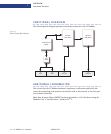
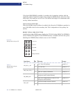
CC1000dm Circuit Board
2-4 CC1000dm User’s Manual 10004281-02
2
Identification Numbers
Before you install the CC1000dm circuit board in a system, you should record the fol-
lowing information:
❐ The board serial number: 680– ______________________________________ .
The board serial number appears on a bar code sticker located on the back of the
board.
❐ The board product identification: ___________________________________ .
This sticker is located near the board serial number.
It is useful to have these numbers available when you contact the Technical Support
department at Artesyn Communication Products.
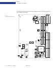
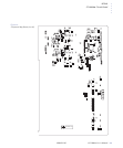
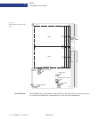
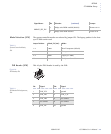
Connectors
The CC1000dm circuit board has various connectors (see the figures beginning on
page 2-3), summarized as follows:
P1–P2:
These connectors are not installed on the CC1000dm.
J1:
This 110-pin connector has keying for 3.3 volt and 5 volt supplies. See Table 4-3 for the
pin assignments.
J2:
This 110-pin connector carries the PCI 64-bit extension signals. See Table 4-4 for the pin
assignments.
J3:
This is a 95-pin connector that routes the I/O signals for the PMC I/O, serial port, and
USB port. See
Table 4-5 for the pin assignments.
J5:
This 110-pin connector is used for PMC I/O. See Table 4-6 for the pin assignments.
J6:
This is a 3-pin header for the Hot Swap switch.
J11:
This connector shares the 32-bit PCI signals with the J12 connector (secondary bus). In
addition, J11 supports a V(I/O) power supply for universal PCI signaling. It uses 3.3 volt
PCI buffers with a 5 volt tolerance. See
Table 3-9 for the pin assignments.
J12:
This connector shares the 32-bit PCI signals with the J11 connector (secondary bus). It
also carries the 3.3 volt supply voltage. See
Table 3-9 for the pin assignments.
J13:
This connector carries the 64-bit PCI extensions (secondary bus). See Table 3-9 for the pin
assignments.
J14:
This connector is for user I/O, which routes to J3. See Table 3-9 for the pin assignments.
J21:
This connector shares the 32-bit PCI signals with the J22 connector (secondary bus). In
addition, J21 supports a V(I/O) power supply for universal PCI signaling. It uses 3.3 volt
PCI buffers with a 5 volt tolerance. See
Table 3-10 for the pin assignments.
J22:
This connector shares the 32-bit PCI signals with the J21 connector (secondary bus). It
also carries the 3.3 volt supply. See
Table 3-10 for the pin assignments.