


PMC/PCI INTERFACE
PMC Connector Pin Assignments
3-14 CC1000dm User’s Manual 10004281-02
3
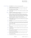
TRDY*:
TARGET READY is a sustained tri-state signal that indicates the target’s ability to com-
plete the current data phase of the transaction.
TRST*:
TEST RESET input signal provides an asynchronous initialization of the TAP controller.
. . . . . . . . . . . . . . . . . . . . . . . . . . . . . . . . . . . . . . . . . . . . . . . . . . . .
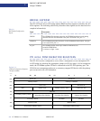
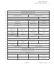
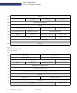
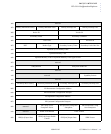
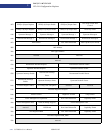
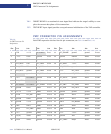
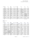
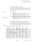
PMC CONNECTOR PIN ASSIGNMENTS
Each PMC expansion slot has four 64-pin connectors, see Table 3-9 and Table 3-10.
Pin: J11: J12: J13: J14: Pin: J11: J12: J13: J14:
.
.
.
.
.
.
.
.
.
.
.
.
.
.
.
.
.
.
.
.
.
.
.
.
.
.
.
.
.
.
.
.
.
.
.
.
.
.
.
.
.
.
.
.
.
.
.
.
.
.
.
.
.
.
.
.
.
.
.
.
.
.
.
.
.
.
.
.
.
1 TCK +12 V no connect P14.1 33 PCI_FRAME* ground ground P14.33
2 -12 V TRST* ground P14.2 34 ground IDSELB AD48 P14.34
3 ground TMS ground P14.3 35 ground PCI_TRDY* AD47 P14.35
4 PCI_INTA* TDO PCI_CBE7* P14.4 36 PCI_IRDY* +3.3 V AD46 P14.36
5 PCI_INTB* TDI PCI_CBE6* P14.5 37 PCI_DEVSEL* ground AD45 P14.37
6 PCI_INTC* ground PCI_CBE5* P14.6 38 +5 V PCI_STOP* ground P14.38
7
no connect ground PCI_CBE4* P14.7 39 ground PCI_PERR* V(I/O) P14.39
8+5 V
no connect ground P14.8 40 PCI_LOCK* ground AD44 P14.40
9PCI_INTD*
no connect V(I/O) P14.9 41 PCI_SDONE* +3.3 V AD43 P14.41
10
no connect no connect PCI_PAR64 P14.10 42 PCI_SBO* PCI_SERR* AD42 P14.42
11 ground PUP0 AD63 P14.11 43 PCI_PAR PCI_CBE1* AD41 P14.43
12 +3.3 V +3.3 V AD62 P14.12 44 ground ground ground P14.44
13 PCLK PCI_RST* AD61 P14.13 45 V(I/O) AD14 ground P14.45
14 ground PDN0 ground P14.14 46 AD15 AD13 AD40 P14.46
15 ground +3.3 V ground P14.15 47 AD12 PCI_M66EN AD39 P14.47
16 GNT* PDN1 AD60 P14.16 48 AD11 AD10 AD38 P14.48
17 REQ* PCI_PME* AD59 P14.17 49 AD9 AD8 AD37 P14.49
18 +5 V ground AD58 P14.18 50 +5 V +3.3 V ground P14.50
19 V(I/O) AD30 AD57 P14.19 51 ground AD7 ground P14.51
20 AD31 AD29 ground P14.20 52 PCI_CBE0* REQB* AD36 P14.52
T
a b l e 3 -9 :
J
1x PMC Connector Pin
A
ssignments