


. . . . .
SETUP
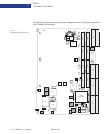
CC1000dm Circuit Board
10004281-02 CC1000dm User’s Manual 2-5
J23:
This carries the 64-bit PCI extensions (secondary bus). See Table 3-10 for the pin assign-
ments.
J24:
This connector is for user I/O, which routes to J5. See Table 3-10 for the pin assignments.
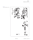
Fuses and Jumpers
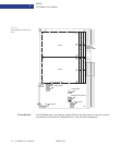
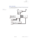
The CC1000dm has various jumpers, headers, and fuses. Please refer to Fig. 2-3 on the
following page for the jumper/header locations.
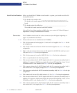
F1-F4:
These are spare fuses on the top side of CC1000dm.
F5:
This fuse (.75 amp) provides protection for the 3.3 volt supply to the PMC JTAG header.
F6:
This fuse (.75 amp) provides protection for the PLD JTAG header.
F7:
This fuse (.75 amp) provides protection for the 5 volt supply to the backplane.
F8:
This fuse (.75 amp) provides protection for the 3.3 volt supply to the backplane.
F9:
This fuse (.75 amp) provides protection for the +12 volt supply to the backplane.
F10:
This fuse (.75 amp) provides protection for the -12 volt supply to the backplane.
JP1, JP2:
Each PMC slot has an associated 10-pin debug header (see Table 3-8).
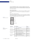
JP3:
This 10-pin jumper selects the following configurations: local VIO, Monarch, auto
memory, oncard oscillator and bridge serial ROM (see page 2 -7).
JP5:
This 4-pin jumper selects the mode: transparent, non-transparent, legacy (Artesyn
CC1000), or no system controller (see page 2-9).
JP6:
The programmable logic device (PLD) uses this 10-pin JTAG header (see page 2-9).
JP7:
This is a spare header.
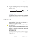
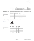
N o t e :
Fuses F5 through F10 are
located on the bottom side,
see Fig. 2-2.