


. . . . .
SETUP
CC1000dm Setup
10004281-02 CC1000dm User’s Manual 2-7
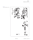
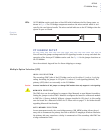
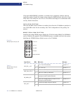
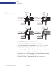
LEDs
All CC1000dm carrier cards have a blue LED which indicates the Hot Swap status, as
shown in
Fig. 2-4. The PCI bridge component monitors the micro-switch which is acti-
vated by the card ejector handle. The micro-switch indicates to the PCI bridge when the
ejector is open or closed.
. . . . . . . . . . . . . . . . . . . . . . . . . . . . . . . . . . . . . . . . . . . . . . . . . . . .
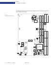
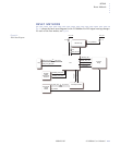
CC1000DM SETUP
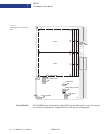
You will need the jumper settings and the PCI signaling in order to set up and check the
operation of the Artesyn CC1000dm carrier card. See
Fig. 2-3 for the jumper locations on
the CC1000dm.
Save the antistatic bag and box for future shipping or storage.
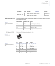
Multiple Option Selection (JP3)
LOCAL VIO SELECTION
The secondary (PMC) side of the PCI bridge can be set for either 3.3 volt or 5 volt sig-
naling. Installing the jumper in JP3 pins 1-2, selects 3.3 volt signaling (default). The
primary (cPCI) side is set externally to the CC1000dm.
Caution: Incorrect installation of this jumper can damage PMC modules that only support 3.3 volt signaling.
MONARCH SELECTION
The PMC slots can be configured to support either Monarch or non-Monarch modules.
Setting the jumper to select PMC1 Monarch configures the board for a Monarch module
in PMC Slot 1 (factory default). Without a jumper installed in JP3 pins 3-4, this config-
ures the board for a Monarch in PMC slot 2. Please refer to page 3-2 for further details
regarding Monarch functionality.
AUTO MEMORY SELECTION
In non-transparent mode, the cross bridge memory (XB_MEM) setting allows the pri-
mary side to enumerate the primary bus with a default 16-megabyte window. Otherwise
the primary side may experience a delay in enumeration if the secondary side PMC has
a long enumeration time.
F i g u r e 2 - 4 :
Front Panel
!