10004281-02 CC1000dm User’s Manual 3-1
. . . . .
. . . . . . . . . . . . . . . . . . . . . . . . . . . . . . . . . . .
PMC/PCI I
NTERFACE
3
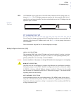
he CC1000dm has two 3.3 volt/5 volt, 64-bit, Processor PMC slots, designated
PMC1 and PMC2. Either slot can be configured as a Monarch module by means
of a ten-pin jumper (see JP3 on page 2 -7). When the CC1000dm is in transpar-
ent mode, neither PMC slot is selected as Monarch. The PMC slots comply with IEEE
Standard for a Common Mezzanine Card Family: CMC IEEE Std 1386-2001.
. . . . . . . . . . . . . . . . . . . . . . . . . . . . . . . . . . . . . . . . . . . . . . . . . . . .
PCI BRIDGE FEATURES
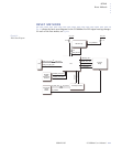
The CC1000dm supports PCI bus speeds of up to 66 MHz with the PLX PCI 6254 (HB6)
dual-mode (transparent and non-transparent), universal 64-bit PCI-to-PCI bridge. In
transparent mode, the PCI bus is connected to the primary port. In non-transparent
mode, the PCI bus is connected to the secondary port. Some additional features include:
• The PLX PCI 6254 bridge complies with the PCI Local Bus Specification Revision 2.3
Bus Interface
• 64-bit PCI address/data busses
• Asynchronous primary and secondary ports can operate at different frequencies–a
maximum ratio of 1:2:5 or 2:5:1 between primary and secondary bus clocks
• Serial ROM interface
•PCI bus arbiter
. . . . . . . . . . . . . . . . . . . . . . . . . . . . . . . . . . . . . . . . . . . . . . . . . . . .
PMC MODULE INSTALLATION
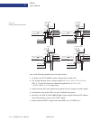
The CC1000dm carrier card has two PMC expansion slots–J1x and J2x (PMC1 and
PMC2). A single-width PMC module may be installed at each of these slots. Each slot
includes a cutout on the front panel for I/O.
When installing a PMC module, follow these guidelines:
1 Before adding modules to the CC1000dm carrier card, be sure that the combined power
requirements of the CC1000dm carrier card and the PMC modules do not exceed the system’s power
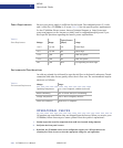
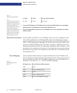
supply rating or cPCI ratings. Table 3-1. describes the power available at the PMC slots.
T


