


SETUP
Reset Methods
2-12 CC1000dm User’s Manual 10004281-02
2
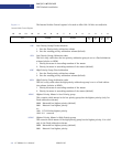
Any of the following methods reset the entire board:
• At power-up, the CC1000dm carrier card generates a hard reset.
• The voltage monitor detects voltage supplies of +5 V, +3.3 V, +12 V,-12 V, or
PMC_3_3V that fall below the minimum thresholds of +4.7 V, +3.1 V,
+11.4 V, -10.8 V, or 3.1 V, respectively.
• Input from the cPCI reset signal (except when in the no system controller mode)
• Pressing the reset switch (SW1) on the CC1000dm front panel
• Writing to the PLX PCI 6254 (HB6) Bridge Control register from the PCI address
space can generate a reset on the S-RST* signal.
• Input from the RSTOUT* signal from either PMC slot 1 or PMC slot 2.
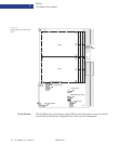
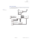
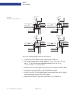
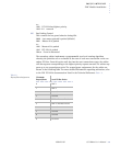
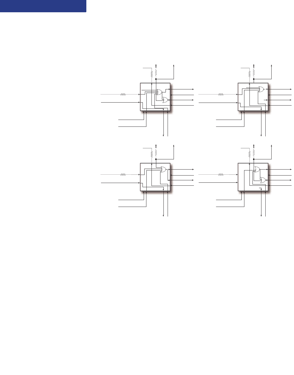
F i g u r e 2 - 8 :
PLD Signal Routing–All Modes
Legacy
Non-transparent
No System Controller
Transparent
PLD
BRIDGE_RST*
BRIDGE_RST_OUT*
S_RSTIN*
S_RSTOUT*
PMC_RSTOUT*
CONN_CPCI_RST
BACKSIDE_PWR_GD
BACKSIDE_PWR_RST*
CONN_CPCI_BD_SEL*
HS_ON*
HS_PWRGD*
PCI_VIO
5.11 K
10 K
CPCI_RST*
10
PCIXCAP_HEALTHY*
(internal signal)
PLD
BRIDGE_RST*
BRIDGE_RST_OUT*
S_RSTIN*
S_RSTOUT*
PMC_RSTOUT*
CONN_CPCI_RST
BACKSIDE_PWR_GD
BACKSIDE_PWR_RST*
CONN_CPCI_BD_SEL*
HS_ON*
HS_PWRGD*
PCI_VIO
5.11 K
10 K
CPCI_RST*
10
PCIXCAP_HEALTHY*
(internal signal)
(1)
PLD
BRIDGE_RST*
BRIDGE_RST_OUT*
S_RSTIN*
S_RSTOUT*
PMC_RSTOUT*
CONN_CPCI_RST
BACKSIDE_PWR_GD
BACKSIDE_PWR_RST*
CONN_CPCI_BD_SEL*
HS_ON*
HS_PWRGD*
PCI_VIO
5.11 K
10 K
CPCI_RST*
10
PLD
BRIDGE_RST*
BRIDGE_RST_OUT*
S_RSTIN*
S_RSTOUT*
PMC_RSTOUT*
CONN_CPCI_RST
BACKSIDE_PWR_GD
BACKSIDE_PWR_RST*
CONN_CPCI_BD_SEL*
HS_ON*
HS_PWRGD*
PCI_VIO
5.11 K
10 K
CPCI_RST*
10
(0)