


. . . . .
SETUP
CC1000dm Setup
10004281-02 CC1000dm User’s Manual 2-9
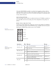
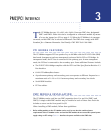
Mode Selection (JP5)
The system controller modes are selected by jumper JP5. The legacy product is the Arte-
syn CC1000 carrier card.
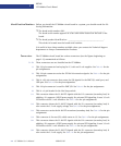
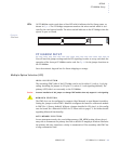
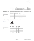
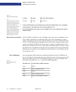
PLD Header (JP6)
This 10-pin JTAG header is used by the PLD.
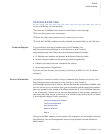
BRIDGE_SEE_EN*
0 Bridge serial ROM enabled (default) Remove 9-10
1 Bridge serial ROM disabled Install 9-10
Jumper Position: Mode_Sel (3:0): Mode:
.
.
.
.
.
.
.
.
.
.
.
.
.
.
.
.
.
.
.
.
.
.
.
.
.
.
.
.
.
.
.
.
.
.
.
.
.
.
.
1-2 1000 Non-Transparent (default)
3-4 1011 Transparent
2-4 0001 Legacy (CC1000)
None 1001 No System Controller
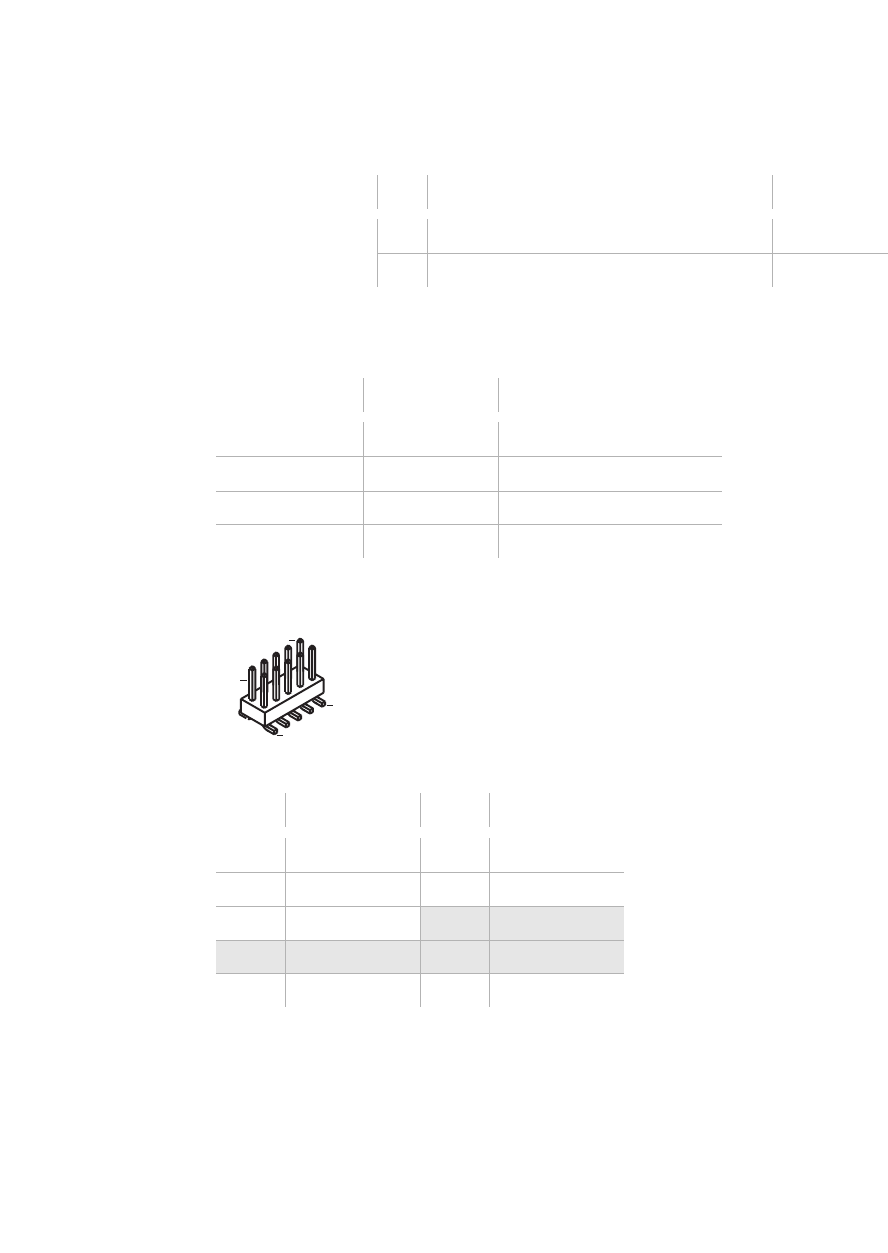
Pin: Signal: Pin: Signal:
.
.
.
.
.
.
.
.
.
.
.
.
.
.
.
.
.
.
.
.
.
.
.
.
.
.
.
.
.
.
.
1 PLD_TCK 2 ground
3PLD_TDO 4PLD_3_3V
5PLD_TMS
6 no connect
7 no connect 8 no connect
9 PLD_TDI 10 ground
Signal Name: Bit: Selection: (continued) Jumper:
.
.
.
.
.
.
.
.
.
.
.
.
.
.
.
.
.
.
.
.
.
.
.
.
.
.
.
.
.
.
.
.
.
.
.
.
.
.
.
.
.
.
.
.
.
.
.
.
.
.
.
Ta b l e 2 - 3 :
System Controller Modes,
JP5
F i g u r e 2 - 6 :
PLD Header, JP6
1
2
9
10
Ta b l e 2 - 4 :
PLD Header Pin Assignments,
JP6