CARRIER CARD BUS INTERFACE
Hot Swap
4-4 CC1000dm User’s Manual 10004281-02
4
Implementation
Individual Hot Swap implementations are differentiated by the Hot Swap resources that
are distributed throughout the system. In order for Hot Swap to be feasible, a board
either being inserted or extracted from a system must not disturb the system power or
the quality of the bus signals.
To prevent power or signal disruption, the CC1000dm requires:
1 Staged Backplane Pins — These pins allow Hot Swap to be implemented in a simple open manner.
Hot Swap compliant backplanes have three pin heights. Long pins are used to provide “early power”
to a board as it is being inserted; this powers the circuitry that controls power-ramping and bus
isolation circuitry. Most signal pins are of medium length. The shortest pin, BD_SEL*, indicates that
a board is fully seated. Systems use this pin to control board power-up.
2 Power-Ramping Circuitry — This ensures that system power is not disturbed when a board is inserted
into a system. It limits in-rush current by ramping the power supplied to the board. This circuitry is
located on peripheral boards.
3 Bus Isolation Circuitry — This ensures that boards that have not been configured do not compromise
the integrity of currently active signals on the backplane. This peripheral board circuitry precharges
signal pins to prevent capacitive draw when the board is inserted.
Other Resources
In addition to the practice of not distributing system power or other signals on a Hot
Swap backplane, Hot Swap systems use other resources to minimize operator interven-
tion when boards are added or removed, or when a board fails.
For example, Hot Swap systems may implement a blue LED on the front panel of a
peripheral board to indicate when it is permissible to remove a board from the system.
Upon insertion of a peripheral board, the LED is on until the hardware connection pro-
cess is completed. The LED then remains off until it is used by the software to indicate
that the board extraction is permitted.
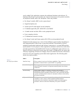
The following signals are also useful:
L_STAT:
STATUS signal monitors the micro-switch which is activated by the CC1000dm card
ejector handle. The micro-switch indicates to the PCI bridge when the ejector is open or
closed. A CC1000dm blue LED indicates the Hot Swap status.
P_ENUM:
ENUMERATION signal indicates that the card has been inserted and is ready for config-
uration, or that the card is about to be removed and should be deactivated by the soft-
ware. This signal is deasserted when the corresponding insertion or removal event bit is
cleared.
P_RST*:
RESET, with the assertion of this input line brings PCI registers, sequencers, and signals
to a consistent state.


