


Appendix A: NT5C10BF-1 and NT5C10BP 103
25A Switch Mode RectifierNT5C06B / C Installation and User Manual
During transfer from a failed “MAIN” unit to a ‘STANDBY” unit the load
current will be supplied by the backup batteries. The standby unit will
provide the required current within 10 seconds.
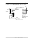
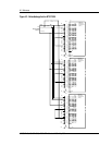
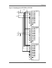
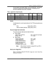
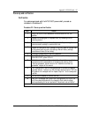
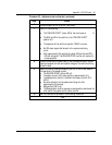
Table 12 - Application configuration table
Rectifier
qty
Function
main/standby
LVD Alarms Current
capacity
1 Main1/None/None No RFA 25 A
2 Main1/Standby/None No RFA/NSR 25 A
2 Main1/None/Main2 No RFA 50 A
3 Main1/Standby/Main2 No RFA/NSR 50 A
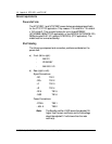
Alarms
Available alarms for monitoring the status of the FTOP power system are as
follows:
- RFA Battery Return (RTN)
- NSR (No Standby Rectifier) Battery Return (RTN)
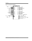
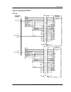
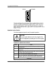
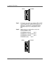
Power and signal lead termination
The power and signal cables are terminated as follows:
a) Power Cables:
- Battery Return (RTN A) TB1-1 (white with red tracer)
-Battery (-48 V A) TB1-2 (red)
b) Signal Cables:
- Negative Sense (RC-) TB1-1 –48 V
- Positive Sense (RG+) TB1-2 RTN
- Jumper1 (see Note below) TB1-3
- Jumper2 (see Note below) TB1-4
- Rectifier Fail (RFA) TB1-5
- No Standby Rectifier (NSR) TB1-6
Note:
When the Main 2 rectifier is missing TB1-3 and TB1-4
must be strapped together.
Factory set voltage limits
Refer to User Manual (UM) 167-7011-010 Voltage Level Limits for Power Plants,
Rectifiers and Controllers.