


70 Low voltage disconnect
UM5C06B / C ( 169-2071-500 ) P0711722 Standard 10.00 May 2001
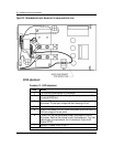
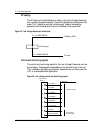
DC cabling
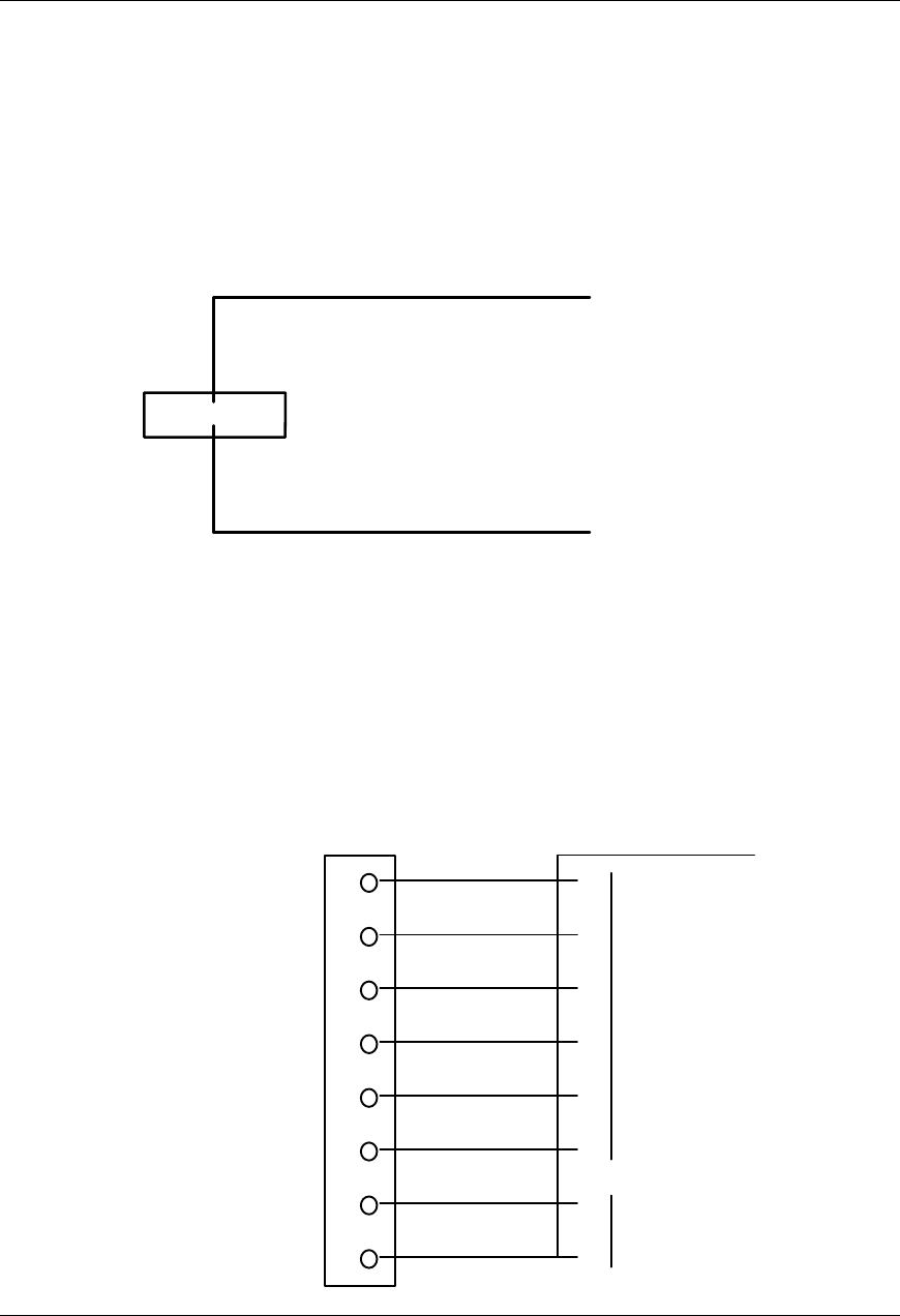
The DC cabling from the batteries, or shelf, to the Low Voltage Disconnect
unit must be connected manually. Figure 25 illustrates the connections to be
made. The “Installation and start up procedure” chapter indicates the
sequence to be followed when the unit is installed in the power shelf.
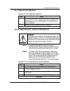
Figure 25 - Low voltage disconnect connections
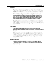
Control and monitoring signals
The control and monitoring signals for the Low Voltage Disconnect unit are
shown below. These signals are accessible on the terminal block in the unit.
The “Installation and start-up procedure” describes how to interconnect the
LVD in an embedded shelf application.
Figure 26 - Low voltage control and monitoring signals
LVDTe
r
mina l
block J1
20 AWG wire
LV ALM NO
LV ALM C
LV ALM NC
LV ALM NO
LVD ALM C
LVD ALM NC
-48 VDC
BAT GRD (RTN)
To Discharge
or Sensing Ckt
To Alarm Monitor
8
7
6
5
4
3
2
1
X
2 x 10
A
WG WIRES
K3 Contactor
To Battery NEG
To Load
2 x 10 AWG WIRES