


Installation and start-up procedures 43
25A Switch Mode RectifierNT5C06B / C Installation and User Manual
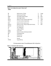
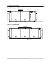
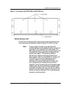
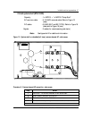
Figure 12 - 19-inch power shelf (NT5C10BF and NT5C10BP only)
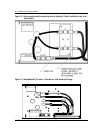
Cabling the power shelf
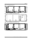
The AC and DC cabling size and routing inside the shelf are determined by
the following shelf configurations. Refer to Figures 13 to 20 for routing.
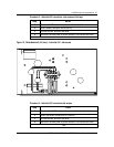
Note:
The grounding of the shelf is provided by the AC
armored cable ground wire attached to a two-hole ground
lug located on the inside wall of the shelf chassis. The
shelf is also grounded to the rack or cabinet frame by one
of the shelf mounting screws which is installed with an
external tooth washer. This grounding method is
sufficient but if desired, an extra ground cable (color
green insulation 105°C), of size 8 AWG for common AC,
or 12 AWG for individual AC applications, can be
installed in addition to the existing cable and be
connected to an external system ground. Using a 0.25-
inch ring lug terminal, the new ground wire can be
installed on one of the existing ground lug screws located
inside the shelf. Route the wire along the inside top back
of the shelf and make it exit out of the right DC cabling
side opening. Ensure the wire does not interfere with the
rectifier connections. See Figure 13 for the extra ground
connection mounting location.