


54 Installation and start-up procedures
UM5C06B / C ( 169-2071-500 ) P0711722 Standard 10.00 May 2001
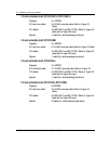
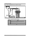
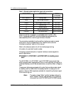
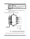
Table 9 - Standard system application signal cable connections:
DESIGNATION DESCRIPTION SIGNAL
ACTIVATES
RG (+) and RC (-) Sensing Leads BAT RTN
HVSD High Voltage Shutdown
HVSDR High Voltage Shutdown Reset BAT RTN
TR Remote Inhibit BAT RTN
EQ Remote Equalize BAT RTN
RFA Rectifier Failure Alarm Form C contacts
FAN ALM Fan Failure Alarm Form C contacts
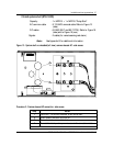
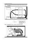
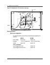
When the rectifier is installed in an embedded shelf, the RC+, RG-,
EQL (if equipped) and RFA monitoring signals are extended by the
cable assembly which is fed through the rear of the shelf.
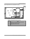
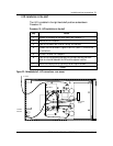
The connections available from the rectifier interface connector located
at the rear of the unit are described in the “Rectifier and controller
interface connections” section of this manual.
Refer to the reference section for all the interface signal wiring
information for each shelf model number.
Following is a brief description of special interface or alarms signals for
specific applications.
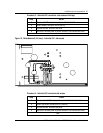
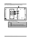
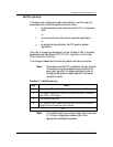
NT5C10BA-1/2, NT5C10BF-1 and NT5C10BP hot standby power
shelf
The NT5C10BA-1/2, NT5C10BF-1 and NT5C10BP wiring is such that
when the power shelf is equipped with two or more rectifiers, one rectifier is
inhibited (Standby) and will be activated when one rectifier (Main or Regular)
fails.
These power shelves are equipped with a relay that provides an alarm signal
no standby rectifier (NSR) when the standby rectifier is missing from its
position. Also two RFA signals are available for transmitting the alarm signal
to the monitoring unit.
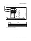
Note :
The earlier vintage "Main" rectifier has been referred to
as the "Regular" rectifier. See Appendix A for additional
information on the NT5C10BF and NT5C10BP shelves.