


41
25A Switch Mode RectifierNT5C06B / C Installation and User Manual
Installation and start-up procedures
Tools and test equipment
The following tools and test equipment are required:
• Potentiometer screwdriver Bourns Inc. No. 32
• Potentiometer screwdriver Bourns Inc. No. 60
• Screwdriver 3 inch
• Digital voltmeter - Fluke 8000 A or equivalent
• Dummy load
Installation procedure
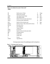
Procedure 1 - Power shelf installation
Step Action
1 Position the power shelf against the rack.
2 Fasten the shelf in the position indicated on the drawings (normally
directly below the Controller or below another power shelf).
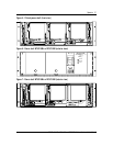
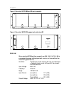
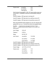
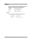
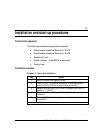
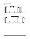
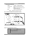
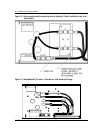
3 Release the clamping bar from the front of the power shelf (Refer to
Figures 10, 11 and 12).
4 Remove the AC junction box cover (left side) and store for re-
installation.
5 Remove the DC and control wiring area cover (right side) and store for
re-installation.
–end–