


66 Installation and start-up procedures
UM5C06B / C ( 169-2071-500 ) P0711722 Standard 10.00 May 2001
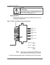
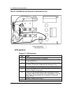
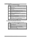
Procedure 16 - Low voltage disconnect adjustment
Step Action
1 Set the NORMAL/BYPASS switch to the BYPASS position. The TEST
LED should light up.
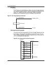
2 Connect a digital voltmeter at the test jacks located at the front/bottom
of the LVD unit.
3 Turn the test potentiometer slowly counterclockwise and verify when
the LVA LED lights up. It should light up at -47 +/- 0.5 V.
4 Continue to turn the test potentiometer counterclockwise until the LVD
LED lights up. It should light at -43.5 +/-0.5 V.
5 Turn the test potentiometer clockwise. At -47 +/-0.5V the LVA LED
should extinguish.
6 Continue to turn the test potentiometer clockwise. Between -50 and -
50.5 V the LVD LED should extinguish.
7 If no adjustment is required, set the NORMAL/BYPASS switch to the
NORMAL position. The TEST LED should extinguish. If any alarm level
must be readjusted, follow the steps described below:
–end–
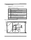
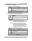
Adjustment for the 50 A LVD unit Rel. 02, 02A, 3 & 3A
Procedure 17 - LVD 50 A adjustment for unit release 02, 02A, 3 and 3A
Step Action
1 Set the NORMAL/BYPASS switch to the BYPASS position (if not already
in the BYPASS position).
2 Remove the LVD unit's faceplate by turning the fastener, located at the
front/top of the unit, one quarter turn counterclockwise.
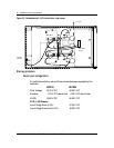
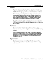
3 Connect the digital voltmeter to the test jacks located at the
front/bottom of the unit's PCB.
–end–