


62 Installation and start-up procedures
UM5C06B / C ( 169-2071-500 ) P0711722 Standard 10.00 May 2001
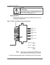
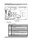
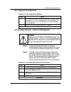
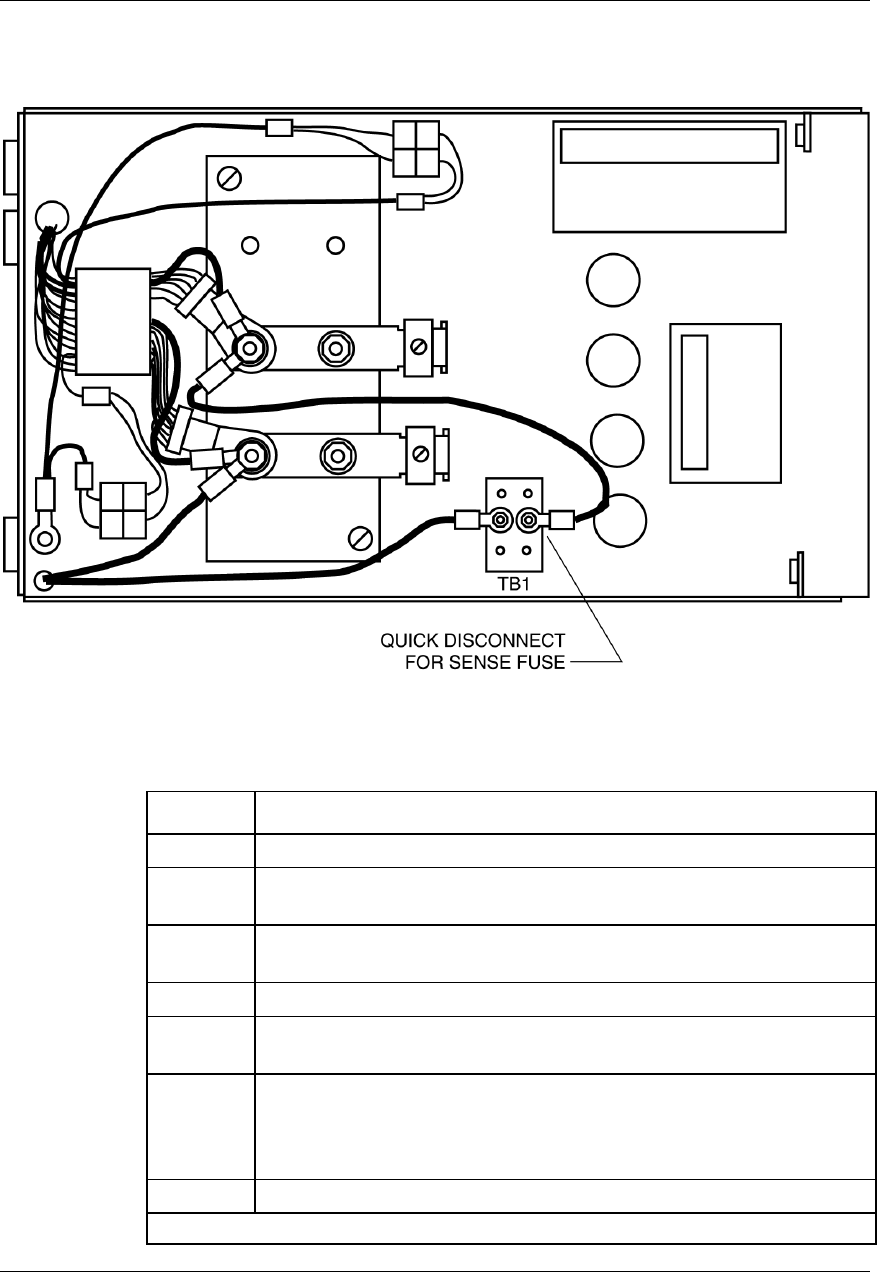
Figure 24 - Embedded shelf quick disconnect for sense (sectional view)
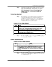
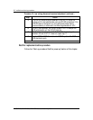
HVSD adjustment
Procedure 12 - HVSD adjustment
Step Action
1 Turn the HVSD potentiometer fully clockwise.
2 Monitoring the test points (V+, V-), adjust the float potentiometer FLT to
the desired HVSD level.
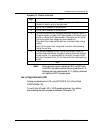
3 Turn the HVSD potentiometer slowly counterclockwise until the rectifier
shuts down. The test point voltage shall start decaying to 0 volt.
4 Turn the float potentiometer counterclockwise, two full revolutions.
5 Cycle the AC breaker OFF/ON. The unit shall power up with the return of
the float voltage on the test points.
6 To verify turn the float potentiometer slowly clockwise until the unit
shuts down. Read the float voltage to verify the disable point. Turn float
potentiometer counterclockwise, two full revolutions. Cycle the AC
breaker OFF/ON.
7 Re-adjust if needed (return to step 1).
–end–