


Installation and start-up procedures 53
25A Switch Mode RectifierNT5C06B / C Installation and User Manual
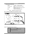
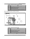
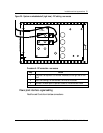
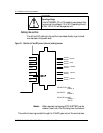
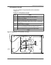
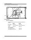
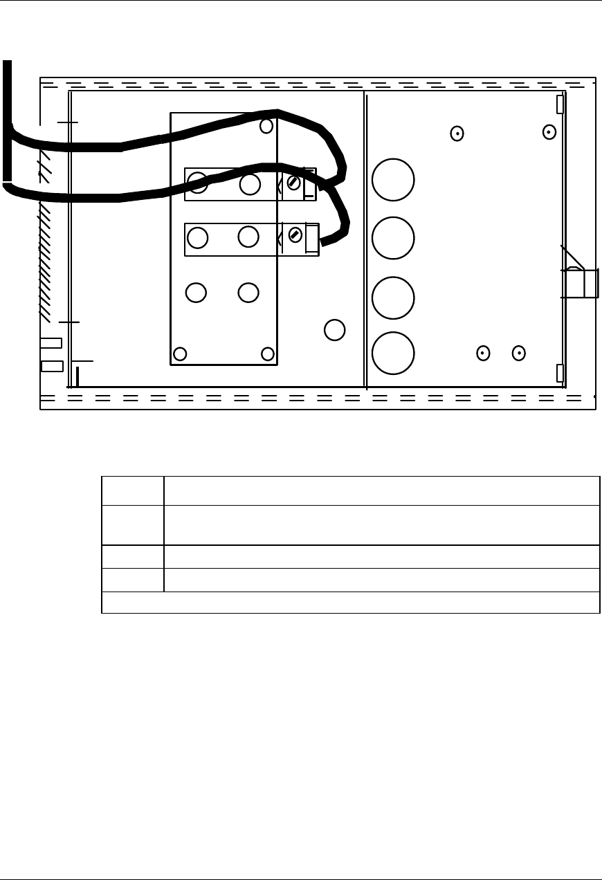
Figure 20 - System or embedded shelf (right view) - DC cabling - rear access
Procedure 8 - DC connection - rear access
Step Action
1 Punch out the top two 0.875-inch dia. knockouts on the right rear of the
shelf.
2 Insert the bushings, run and connect the wires as illustrated.
3 Re-install the blank panel to prevent access to the connections inside.
–end–
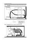
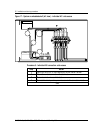
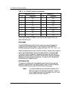
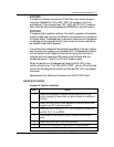
Power plant interface - signal cabling
Rectifier and Controller interface connections.
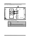
BR
(+VDC)
B
A
T
(-VDC)