


Installation and start-up procedures 45
25A Switch Mode RectifierNT5C06B / C Installation and User Manual
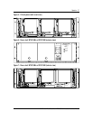
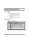
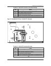
19-inch embedded shelf (NT5C10BA-5/6,NT5C10BB-3/4)
Capacity: - 2 x MPR25 + LVD
AC common cable - 2/8AWG armored cable. Reference Figure 13
DC cables - 6 AWG (BAT and BAT RTN). Refer to
Figure 19 (Side) and to Figure. 20 (Rear)
Signals: - 1 cable (for remote sensing and alarm)
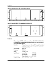
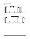
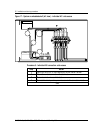
19-inch embedded shelf (NT5C10BB-1/2)
Capacity: - 2 x MPR25 + LVD
AC common cable: - 2/12 AWG armored cable. Refer to Figure 13
DC cables: - 6 AWG (BAT and BAT RTN). Refer to
Figure 19 (Side) and to Figure 20 (Rear)
Signals: - 1 cable (for remote sensing and alarm)
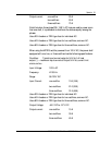
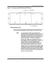
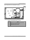
23-inch system shelf (NT5C10CB-1/2, NT5C10CB-5/6, NT5C10CC-1/2,
NT5C10CD-1/2) NT5C10CG
Capacity: - 3 x MPR25
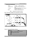
AC common cable: - 2/6 AWG armored cable. Refer to Figure 13 (side)
DC cables: - 4 AWG (BAT and BAT RTN). Refer to Figure
19(side) and to Figure 20 (rear)
Signals: - 2 x 8 conductor cables terminated with
connectors.
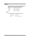
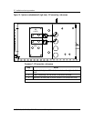
23-inch system shelf (NT5C10CB-3/4, NT5C10CE, NT5C10CF, NT5C10CH)
Capacity: - 3 x MPR25
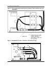
AC individual cable - 2/12 AWG armored cable. Refer to Figure 17.
DC cables - 4 AWG (BAT and BAT RTN). Refer to Figure 19
(side) and to Figure 20 (rear)
Signals: - 2 x 8 conductor cables terminated with
connectors.
23-inch embedded shelf (NT5C10BC-1/2)
Capacity: - 3 x MPR25
AC individual cable: - 2/12 AWG armored cable. Refer to Figure 16
DC cables: - 4 AWG (BAT and BAT RTN). Refer to Figure
19(side) and to Figure 20 (rear)
Signals: - 1 cable (for remote sensing and alarm)