


Installation and start-up procedures 63
25A Switch Mode RectifierNT5C06B / C Installation and User Manual
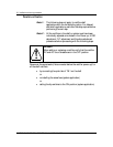
Note:
If the desired HVSD level is greater than the –57 V float
limit, hold the FLT/EQL switch to EQL and use the
EQL potentiometer to bring the float voltage to the
desired HVSD level. Hold the switch through the
following steps.
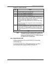
Float voltage adjustment
Note:
For installation where rectifiers can be connected to the
charge bus (all rectifiers with DC breakers ON and
remote sense leads connected) prior to final adjustment,
Procedure 13 can be omitted and be performed in the
“Parallel verification” procedure section.
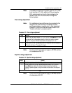
Procedure 13 - Float voltage adjustment
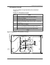
Step Action
1 Adjust the float potentiometer FLT to 0.5 volt DC (see Note below) above
the desired float voltage determined by the battery vendor or power
engineer, using the voltmeter attached to the test point (V+ V-).
2 Final system’s float voltage adjustment will be performed as indicated in
“Parallel verification” Procedure15, step 4.
–end–
Note:
The 0.5 volt DC extra does not apply to MPR25 rectifiers
of a release above Rel: 30.
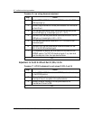
Equalize voltage adjustment
Procedure 14 - Equalize voltage adjustment
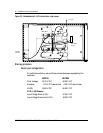
Step Action
1 Hold the equalize switch in the EQL position.
2 While the switch is up, set the equalize potentiometer to 0.5 volts DC
(see Note below) above the desired level determined by the battery
vendor or power engineer, using the voltmeter attached to the test point
(V+ V-).
–end–
Note:
The 0.5 volt DC extra does not apply to MPR25 rectifiers
of release above Rel: 30.