Installation and start-up procedures 55
25A Switch Mode RectifierNT5C06B / C Installation and User Manual
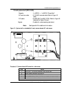
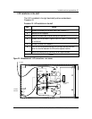
NT5C10BA-3/4 special operating signal - AC fail NC
Originating from a time delay relay, this signal indicates the state of the line
input voltage of the left rectifier in the shelf. This relay, which is normally
closed, will open after a delay of 8 to 10 seconds following the removal of
the AC line input. The indicator should be set to #6.
Note :
The standby HVSD rectifier should be adjusted 0.5 V
higher than the main rectifier, and its float voltage 0.1 V
lower than the main rectifier.
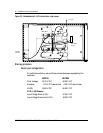
NT5C10BJ & NT5C10BK
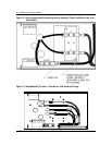
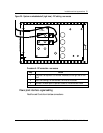
The NT5C10BJ and NT5C10BK power shelves (23-inch mounting) are
designed for embedded applications. The NT5C10BJ is brown and the
NT5C10BK is dolphin grey. Both power shelves can be equipped with two
MPR15 and MPR25 rectifiers and a low voltage disconnect unit
(NT6C13FC), or with two rectifiers, one RPM1000C and one low voltage
disconnect unit without a control circuit pack (NT6C13FJ).
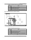
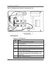
When the NT6C13FJ unit is used, the RPM1000C performs the control
and monitoring functions. The NT6C13FJ is equipped with an interface
circuit pack that receives the LVD signal from the RPM1000C (battery
return) to open the LVD contactor. It is equipped with a bypass switch.
The function of the BYPASS switch is to prevent accidental release of
the LVD contactor during maintenance, or when the RPM1000C is
being replaced.
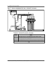
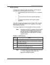
The power shelves are offered in the two configurations described above.
When the RPM1000C is not provided, the power shelf is equipped with the
NT5C10PC interface circuit pack. The function of this circuit pack is to
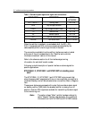
connect the rectifier control cables (J1 and J2) and the alarm cable (J3). The
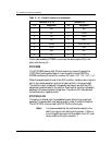
connector pin assignments are listed in Table 10.


