


Installation and start-up procedures 57
25A Switch Mode RectifierNT5C06B / C Installation and User Manual
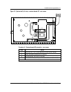
NT5C10KC
This option is offered to provide an AC Fail Alarm upon loss of the input
line power. Selectable for 120 or 208 / 280 V AC operation, the circuit
provides a dry C form contact relay, TB1-1 (NC) and TB1-2 (C), to send an
alarm. See User Manual (UM) supplement P0803489 for more information.
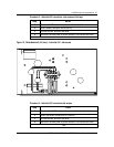
NT5C10CO
This power shelf houses two rectifiers. One rectifier operates in the standard
mode (no delay) and the other is inhibited for a fixed amount of time after an
AC power failure. The delayed start is required to allow time for the batteries
to recharge, and the required total AC input current for the two rectifiers to
be reduced to less than 20 amperes.
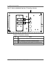
The rectifier that is delayed will be activated immediately if the main rectifier
fails, is pulled out or missing, or produces an RFA. The delayed start rectifier
will not transmit an RFA signal to the controller during the time that it is
inhibited, but it will transmit an RFA signal to the Controller after the
delayed start period, if the DC or AC circuit breaker is open.
When the rectifier is on the delayed start mode, the RFA LED on the
rectifier will be lit (red). The “DELAYED START” yellow LED of the timer
will be ON indicating that the rectifier with the red RFA LED is on delayed
start mode.
See Appendix B for additional information on the NT5C10CO shelf.
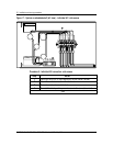
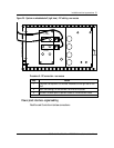
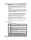
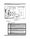
Installing the rectifier
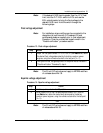
Procedure 9 - Rectifier installation
Step Action
1 Release the clamping bar and remove the blank panel with a lifting
motion, dislodging the lower tables, and place the panel at the bottom of
the shelf.
2 Ensure that the AC and DC circuit breakers of the rectifier (about to be
plugged in) are OFF (in the down position).
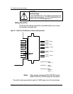
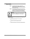
3 Ensure that the AC line input is 110 / 120 V AC nominal for the MPR15
and 208 / 240 V for the MPR25.
4 Slide the rectifier into the shelf, resting it on top of the stored blank
panel.
5 Ensure that the rectifier is firmly slid into position.
6 Re-install the clamping bar by tightening the two captive screws.
–end–