


76 Maintenance
UM5C06B / C ( 169-2071-500 ) P0711722 Standard 10.00 May 2001
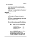
Load sharing
Verify that the sense leads of all the rectifiers are connected to a common
point (across the battery or output power terminals of the power shelf, or at
the discharge busbar).
Readjust the rectifier’s float voltage until all the rectifiers share the load. It is
recommended that the current from each rectifier be 3 amperes minimum
for best results.
It is also recommended to leave the units functioning for at least 30 minutes
to reach full stability, prior to final system adjustment.
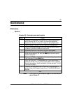
Fan failure
Fan failure is indicated by the absence of fan rotation. The rectifier will be
inhibited and an RFA and Fan alarm will be activated. The Fan Fail LED will
turn RED.
Fan replacement procedure
DANGER
Before replacing the fan, turn the rectifier off. Remove the
rectifier from the shelf. Wait five minutes to allow all
internal capacitors to fully discharge.
CAUTION
Take the necessary precautions to prevent any dirt, dust,
moisture, or metallic particles from falling into the unit.
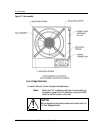
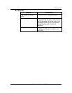
Procedure 21 - Fan replacement
Step Action
1 With the unit sitting solidly on a clean workbench, carefully remove the
five mounting screws that secure the fan assembly (see Figure 27).
2 Slowly and carefully remove the fan assembly by pulling it from the
chassis.
3 Take note of which side the wire is connected to the fan and disconnect
the fan connector (three pins).
continued