


104 Appendix A: NT5C10BF-1 and NT5C10BP
UM5C06B / C ( 169-2071-500 ) P0711722 Standard 10.00 May 2001
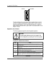
General requirements
Power shelf size
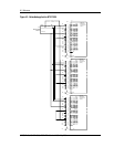
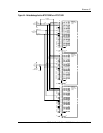
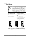
The NT5C10BF-1 and NT5C10BP power shelves are designed specifically
for the FTIP/FTOP application. They measure 17.0 inches W x 7.0 inches H
x 12.0 inches D. They provide housing for up to three MPR25EX
(NT5C06BB) SMRs (FTOP application), or two MPR15E (NT5C06CB/CD)
SMRs plus one 50 A LVD module (NT6C13FA) (FTIP application). The
middle rectifier is wired as Standby.
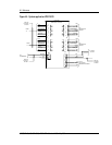
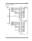
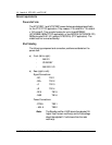
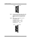
Shelf labeling
The following component and connection positions are labeled on the
power shelf:
a) Front (left to right):
- MAIN1
- STANDBY
- MAIN2/LVD
b) Rear (right to left):
Signal Connections:
- RC- TB1-1
- RG+ TB1-2
- J1 TB1-3
- J2 TB1-4
- RFA TB1-5
- NSR TB1-6
Power Connections:
- RTNA TB2-1
- -48V A TB2-2
Note:
The Standby rectifier HVSD should be adjusted 0.5
higher than the main rectifier(s) and its float voltage
should be adjusted 0.1 volts lower than the main
rectifier(s).