


Appendix B: NT5C10CO shelf 109
25A Switch Mode RectifierNT5C06B / C Installation and User Manual
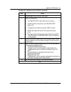
Procedure 23 - Adjustment and verification ( continued )
Step Action
6
Close and open the SW1-6 switch (timer reset).
7
Verify for the following:
• The "DELAYED START" yellow LED at the circuit pack is lit.
• The RFA red LED of the rectifier at the "DELAYED START"
position is lit.
• The operation of the rectifier at position "MAIN" is normal.
• No RFA alarm signal shall be sent to the system monitoring
circuit.
• After approximately 30 seconds the yellow LED and the red (RFA)
LED will extinguish. The DELAYED START rectifier will resume its
normal operation
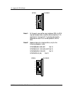
8 Connect an external 6 ampere load (or use a telecommunication system
load) and readjust the float and equalize voltage of the rectifiers so they
share the load.
9 Reset the timer by closing and opening the SW1-6 switch and observe
the operation of the power system:
• The DELAYED START yellow LED is lit.
• The output current of the main rectifier is approximately 6 A.
• The delayed start rectifier is inhibited. Zero output current. RFA
LED lit.
• No alarm indication on the system monitoring unit after
approximately 30 seconds:
• Delayed Start LED is off.
• The Delayed start rectifier resumes normal operation and shares the
total load of the system with the other rectifier.
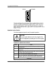
10 Set the timer switch as shown in the following illustration.
–end–