


56 Installation and start-up procedures
UM5C06B / C ( 169-2071-500 ) P0711722 Standard 10.00 May 2001
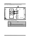
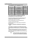
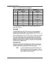
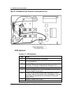
Table 10 - J1, J2 and J3 connector pin assignment
Connector J1 & J2 Connector J3
Pin Assignment Pin Assignment
1 EQL 1 EQL
2 RG+ 2 HVSDR
3 RC- 3 HVSD
4 N/C 4 RFA1
5 HVSDR 5 LOGIC RETURN
6 HVSD 6 RFA2
7 RFA 7 N/C
8 N/C 8 LVA
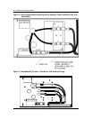
Order cable assembly P0739814 to connect the alarm signals (J3) to the
alarm monitoring unit.
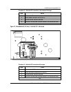
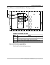
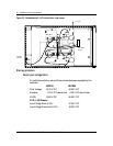
NT5C10BM
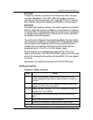
The NT5C10BM power shelf (23 inch mounting) is wired to accept the
NT5C10KB local equalize feature. It can house up to three MPR15 or
MPR25 rectifiers and is wired for common AC input, 120 / 208 / 240 V AC.
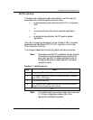
When the equalize switch is set to the EQL position, a battery return signal is
sent to the remote equalize input port of each rectifier in the power shelf.
The rectifier output voltage will increase by the amount set with the EQL
adjustment potentiometer of the rectifier. Each rectifier must be individually
adjusted to the same equalize voltage level. The yellow LED indicates that
the rectifiers are in equalize mode.
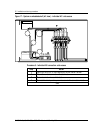
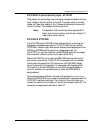
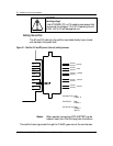
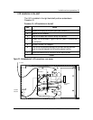
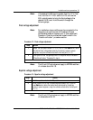
NT5C10KA & KB
This option is offered with the embedded power shelves to provide local
equalize. The power shelf must be pre-wired in order to install this feature.
The NT5C10KA is brown and the NT5C10KB is oxford grey.
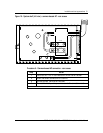
Note :
It is recommended that the rectifiers be inserted in the
shelf from right to left, starting with position 1. When a
Low Voltage Disconnect unit is available, the LVD must
be mounted to the right of position 1.