


68 Installation and start-up procedures
UM5C06B / C ( 169-2071-500 ) P0711722 Standard 10.00 May 2001
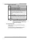
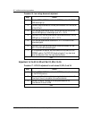
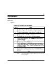
Procedure 19 - Low voltage disconnect/reconnect adjustment ( continued )
Step Action
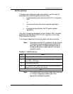
5 The LVD LED should extinguish between -50 and -50.5 V. Adjust the
voltage with the test potentiometer until the LVD LED extinguishes. If the
LVD LED does not extinguish, turn the LVDR potentiometer slightly
counterclockwise, or clockwise if the LED extinguishes before –50 V.
6 To verify the adjustment, set the test voltage to -43.5 V. Readjust the
LVD potentiometer until the LVD LED lights up.
7 Readjust the test voltage to –51 V. The LVD LED should extinguish
between -50 and -50.5 V. If it does not, repeat step 17.
8 Set the NORMAL/BYPASS switch to the NORMAL position. The TEST
LED should extinguish.
–end–
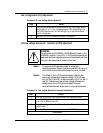
Rectifier replacement/add-on procedure
Follow the “Start-up procedure: Rectifier power up”section of this chapter.