


Maintenance 75
25A Switch Mode RectifierNT5C06B / C Installation and User Manual
Low voltage disconnect
The LVD voltage adjustment levels should be verified periodically
(preferably at intervals no greater than one year). Refer to the “Fault
diagnosis” section found at the end of this chapter for the verification
procedure. When the verification has been completed, set the Test/Bypass
switch to the Normal position.
The DC connections on the main contactor should be tightened with a torque
wrench set at 70 in.-lb. periodically (at one-year intervals) to avoid the build
up of hot spots and voltage drops.
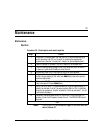
Troubleshooting
Rectifier fail alarm
Verify that the input AC voltage is within the specified limits.
Cycle the AC breaker off/on to reset the unit from a possible HVSD
shutdown.
Make sure the HVSD potentiometer is adjusted properly. Refer to the “Start-
up procedure” section of the “Installation and start-up procedure” chapter of
this manual for the adjustment procedure.
If the unit is used in parallel with other units the rectifier may indicate an
RFA alarm when the unit produces no current (see
Note
below). This could
mean that the float voltage is too low. Increase the float voltage by turning
the FLT potentiometer clockwise until the ON/RFA led turns green.
Note:
Triggers an alarm at no load condition, only for the
following releases, or under.
NT5C06BB,BB-1,BB-3,BC Rel.10
NT5C06CA,CA-1,CA-3,CA-5,CC Rel.10
NT5C06CB,CB-1,CB-3,CD Rel.12
NT5CO6CE-61(-46) Rel.12
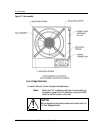
- Verify the front panel inrush current fuse (F1, 3/4 A, 250 V). A
blown fuse on the MPR15E (NT5C06CB/CD/CE) may indicate that
the input line voltage is too high. Refer to “Appendix C:
Recommended replacement parts” to order a replacement fuse.
- The unit must not be opened for on-site servicing. If a problem
persists contact your local Astec representative.