


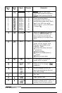
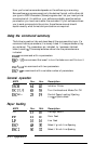
Signal
Return Signal
Direction Description
Pin
Pin
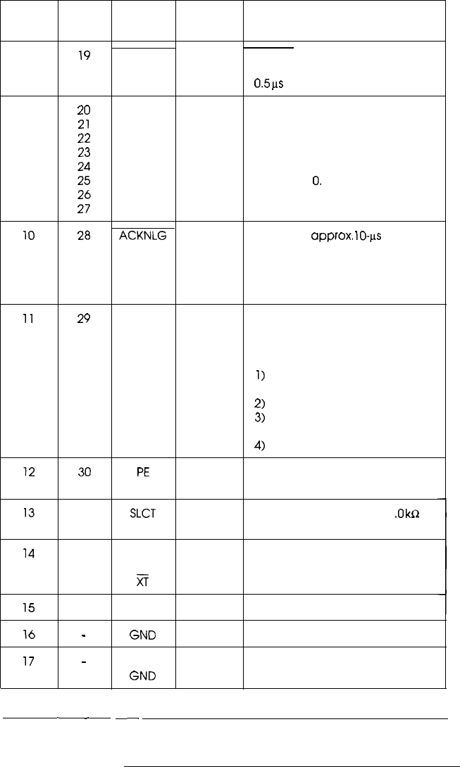
1
19
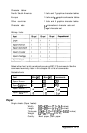
STROBE
IN
STROBE pulse to read data.
Pulse width must be more than
0.5
ps
at the receiving terminal.
2 20 DATA 1
IN
These signals represent
3
21
DATA 2
IN
information in bits 1 to 8 of
4 22
DATA 3
IN
parallel data respectively. Each
5 23
DATA 4
IN
signal is at HIGH level when
6 24
DATA 5
IN
data is logical 1 and LOW when
7
25 DATA 6
IN
it is logical
0.
8
26 DATA 7
IN
9
27
DATA 8
IN
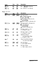
10
28 ACKNLG
OUT About an
approx.
lo-l.ts
pulse.
LOW indicates that data has
been received and that the
printer is ready to accept more
data.
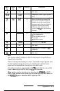
11
29 BUSY
OUT A HIGH signal indicates the
printer cannot receive data.
The signal goes HIGH in the
following cases:
1)
During data entry (for each
character)
2)
During printing
3)
When the PAUSE button is
pressed
4)
During an error state
12
30
PE
OUT A HIGH signal indicates the
printer is out of paper.
13
- SLCT
OUT
Pulled up to 5 V through 1
.O
kR
resistance
14
, -
AUTO
FEED
i?
IN
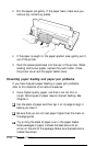
When this signal is LOW, the
paper is automatically fed one
line after printing.
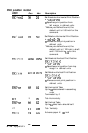
15
-
NC
Not used
16
-
GND
-
Logic ground level
17
-
’
CHASSIS -
Printer’s chassis ground, which is
GND
isolated from the logic ground
.-_
~
A-8 Appendix