


Communication Interfaces 10-7
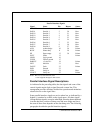
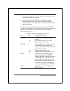
Parallel Interface Signals
Signal Name Pin Return Source
STROBE- Data strobe 1 19 Host
DATA1 Data bit 1 2 20 Host
DATA2 Data bit 2 3 21 Host
DATA3 Data bit 3 4 22 Host
DATA4 Data bit 4 5 23 Host
DATA5 Data bit 5 6 24 Host
DATA6 Data bit 6 7 25 Host
DATA7 Data bit 7 8 26 Host
DATA8 Data bit 8 9 27 Host
ACK- Acknowledge 10 28 Printer
BUSY Printer busy 11 29 Printer
PE Paper empty 12 30 Printer
SLCT Select 13 Printer
LGND Logic ground 16
CGND Chassis ground 17
PARVCC +5 volts dc* 18 Printer
INIT- Initialize 31 Host
FAULT- Fault 32 Printer
GND Ground 33
VFIN Verify in 34 Host
VFOUT Verify out 35 Printer
Notes: Pins 14, 15, and 36 are not used.
*+5vdc supplied through 51 ohm resistor.
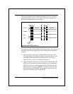
Parallel Interface Signal Descriptions
As indicated in the preceding table, the data signals and some of the
control signals require both a signal line and a return line. This
arrangement provides efficient, trouble-free operation and minimizes
electrical noise on the signal lines.
Some parallel interface signals are active when low, as indicated by a
hyphen (-) attached as a suffix to the signal name. All other signals
(except the data signals) are active when high. Since the data transferred
over the data lines consists of binary ones and zeros (highs and lows),
the state of these lines depends on the data being sent. The following
paragraphs describe the parallel interface signals.