


Installing a BlackDiamond 8800 Series Module
BlackDiamond 8800 Series Switches Hardware Installation Guide
105
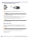
● If the captive screw on each handle has a yellow band around the head of the screw, turn the
screw on each injector/ejector handle clockwise and completely down. When the screw is fully
tightened, the yellow band around the captive screw is completely hidden.
CAUTION
Be careful to avoid over-torquing and stripping the screw heads.
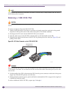
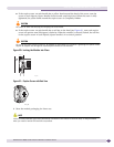
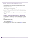
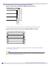
● If the captive screw on each handle has a red line on the head (see Figure 61), turn each captive
screw one-quarter turn (90 degrees) clockwise. When the module is correctly locked, the red line
on the captive screw in each injector/ejector handle is in a vertical position.
CAUTION
Be sure to turn each captive screw only 90 degrees or one-quarter turn clockwise. Tightening the captive screws
beyond 90 degrees will damage the injector/ejector handles on the modules.
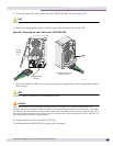
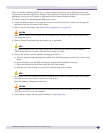
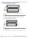
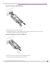
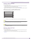
Figure 60: Locking the Module into Place
Figure 61: Captive Screw with Red Line
9 Store the module packaging for future use.
NOTE
Leave the ESD-preventive wrist strap permanently connected to the chassis so that the strap is always available
when you need to handle ESD-sensitive components.
EX_125
EX_162