


Installing Modules and Establishing Initial Management Access
BlackDiamond 8800 Series Switches Hardware Installation Guide
106
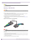
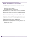
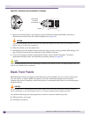
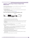
Making Network Interface Cable Connections
Use the appropriate type of cable to connect the ports of your switch to another switch or router.
Working carefully, one port at a time:
1 Verify that you have identified the correct cable for the port.
2 Use an alcohol wipe or other appropriate cleaning agent to clean the cable connectors; make sure
they are free of dust, oil, and other contaminants.
3 If you are using optical fiber cable, align the transmit (Tx) and receive (Rx) connectors with the
correct corresponding connectors on the switch or the I/O module.
4 Press the cable connectors into their mating connectors on the switch or I/O module until the cable
connector is firmly seated.
5 Repeat steps 1 through 4 for the remaining cables on this or other switches or I/O modules.
6 Dress and secure the cable bundle to provide appropriate strain relief and protection against bends
and kinks.
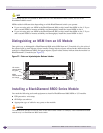
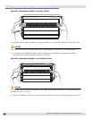
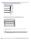
Connecting and Disconnecting Cables on the 10G4Ca Module
The ports on the 10G4Ca I/O module use copper CX4 interface connectors. The cables that connect to
these ports include a latch that mechanically stabilizes the connection. You must be sure to correctly
engage the latch when you connect cables, and to correctly disengage the latch when you disconnect
cables.
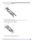
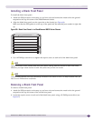
To connect cables to the 10G4Ca module:
1 Make sure that the connector latch is pulled back to the unlatched position.
2 Align the connector with the module port and push it into place until the connector is flush with the
front panel of the module (Figure 62).
3 Evenly push the latch toward the module port to secure the connection (Figure 62). Make sure that
the latch engages equally on both sides.