


Meeting Site Requirements
BlackDiamond 8800 Series Switches Hardware Installation Guide
59
At a minimum, follow these guidelines to ground equipment racks to the earth ground:
● CAD weld appropriate wire terminals to building I-beams or earth ground rods.
● Use the appropriate chassis grounding wire for your system, which is dependant upon the available
input current to the power supply.
■ For AC systems using a 20A breaker per PSU (SSI AC), the chassis ground can be as small as
14 AWG. The power cable ground should be the same size as the primary.
■ For DC systems using a 15A breaker per PSU (Summit X450a-48tDC switch), the chassis
ground can be as small as 14 AWG. The power cable ground should be the same size as the
primary.
■ For DC systems using a 40A breaker per PSU (SSI DC), the chassis ground can be as small as
10 AWG. The power cable ground should be the same size as the primary.
NOTE
For complete details on power supplies and power supply cords, refer to the following: Chapter 4, “Power Supply
Units for BlackDiamond 8800 Series Switches,” and “Selecting Power Supply Cords” on page 158 in Appendix
A, “Safety Information.” Drill and tap wire terminals to equipment racks.
● Position the earth ground as close to the equipment rack as possible to maintain the shortest wiring
distance possible.
● Use a ground impedance tester or micro-ohm meter to test the quality of earth ground connection at
the chassis. This will insure good grounding between the chassis, rack, and earth ground.
NOTE
Because building codes vary worldwide, Extreme Networks strongly recommends that you consult an electrical
contractor to ensure proper equipment grounding for your specific installation.
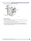
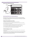
Space Requirements for the Rack
Provide enough space in front of and behind the switch so that you can service it easily. Allow a
minimum of 48 inches (122 cm) in front of the rack and 24 inches (61 cm) behind the rack. When using a
relay (two-post) rack, provide a minimum of 24 inches (61 cm) of space behind the mounted equipment.
Extra room on each side is optional.
WARNING!
The chassis does not have a switch for turning power to the unit on and off. For systems using an AC power supply,
power to the chassis is disconnected by removing the wall plug from the electrical outlet. For systems using a DC
SSI power supply, power to the chassis can be turned off by lifting the handle on the power supply or by de-
energizing the circuit that feeds the power supply, which is usually accomplished by turning off a circuit breaker.
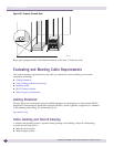
Securing the Rack
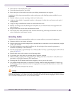
The rack should be attached to the wiring closet floor with 3/8-inch (9.5 mm) lag screws or equivalent
hardware. The floor under the rack should be level within 3/16-inch (5 mm). Use a floor-leveling
cement compound if necessary or bolt the racks to the floor as shown in Figure 30.