


Installing Modules and Establishing Initial Management Access
BlackDiamond 8800 Series Switches Hardware Installation Guide
110
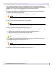
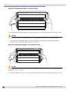
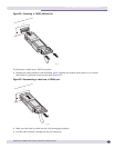
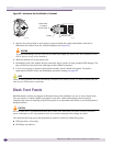
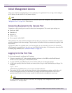
Figure 65: Indications that the Module is Unlocked
3 Squeeze the release latch on each injector/ejector handle and rotate both handles outward to
disconnect the module from the chassis backplane (see Figure 65).
CAUTION
To prevent ESD damage, hold the module by the metal panel edges only. Never touch the components on the
PCB or the pins on any of the connectors.
4 Slide the module out of the chassis slot.
5 Immediately place the module into the anti-static bag to protect it from potential ESD damage. The
bag will also prevent dust from collecting on the module connectors.
6 If you are not going to install a replacement module, install a blank front panel. To install a
replacement module, follow the installation procedure starting on page 102.
NOTE
Leave the ESD-preventive wrist strap permanently connected to the chassis so that it is always available when you
need to touch ESD-sensitive components.
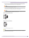
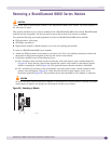
Blank Front Panels
BlackDiamond switches are shipped with blank front panels installed over one or more chassis slots.
You can remove or install a blank front panel at any time without disrupting network services.
Complete the action of installing a blank front panel in a reasonable time-frame to avoid disruption to
adequate airflow.
CAUTION
All unoccupied slots in a BlackDiamond 8800 series switch must have blank front panels correctly installed to
ensure conformance to FCC requirements as well as to maintain adequate airflow through the switch.
You need the following tools and equipment to install or remove a blank front panel:
● ESD-preventive wrist strap
● #2 Phillips screwdriver
EX_173
Release Latch
Handle
Yellow Band
on Captive
Screw Head
EX_161