


Installation
This section describes the installation and the operation of the MPS601, including:
• Mounting the Switcher
• Connections
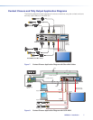
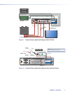
• Contact Closure and Tally Output Application Diagrams
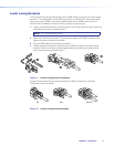
• Lockit Lacing Brackets
• Cabling the MPS601 Switcher
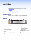
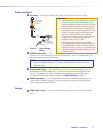
Mounting the Switcher
The MPS601 is housed in a 1U, full rack widthrack- or desk-mountable metal enclosure.
The switchercan also be surface-mounted under a table, desk, or podium, or on a wall.
See Mounting Options on page44 for additionalmounting details.
Connections
0.5 A MAX
POWER
12V
1
2
B
A
3
4
5
6
INPUTS
MPS 601
CONTACT IN / TALLY OUT
HDMI
RGBHV
HDMI
HDMI
RS-232
GC
135
246
TTCG TCG
GCT TCG T
+V
CG
TxRx G
OUTPUT
REMOTE
AABBCCDDEEF
FG
G
HH
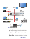
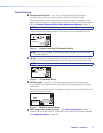
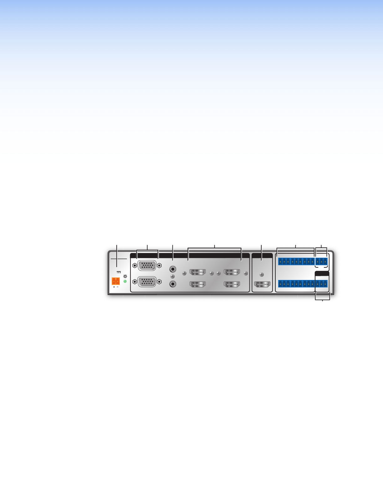
Figure 2. MPS601 Rear Panel
Power and Input Connections Output Connection Control Device Connections
A
DC power connector.
E
One female HDMI connector.
F
Contact In/Tally Out — Six
3.5mm, 3-pole captive screw
connectors for automatic input
switching and tally indication using
Extron Show Me cables.
B
Two Configurable analog 15-pin HD
(VGA) connectors.
C
Two female 3.5 mm TRS connectors
(lettered A and B on the rear panel)
corresponding to the two RGBHV
video inputs.
G
+V Port — 3-pole 3.5mm captive
screw connector for +V output.
D
Four female HDMI connectors for HDMI compliant audio
and video input (numbered 3, 4, 5, and 6 on the rear
panel).
H
RS-232 — 3-pole, 3.5mm captive
screw connector.
MPS601 • Installation 4