


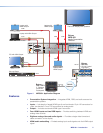
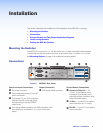
Control Devices
F
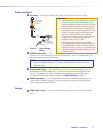
Contact In and Tally Out — Six 3.5 mm, 3-pole captive scrw connectors for
automatic input switching and tally indication using Extron Show Me cables.
When a connected contact is grounded, the corresponding input is selected. At the
same time, the tally output closes causing the Show Me LED on the connected cable to
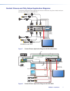
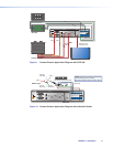
light (see Contact Closure and Tally Output Application Diagrams on page7).
NOTE: For Show Me cables, the ground pin connection is optional.
The six contacts are mutually exclusive so that only one input is selected at at time.
Ground (G)
Tally (NO)
Contact (NO)
TC G
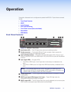
Do not tin
the wires!
Figure 4. Contact In and Tally Out Connector Wiring
NOTE: Do not tin the leads. Tinned wires are not as secure in the connector and
could be pulled out.
G
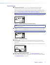
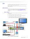
+V Port — 3-pole, 3.5 mm captive screw connector. The three pins constantly output
+5 VDC, 200mA total (shared between pins) to provide power for external tally LEDs.
NOTE: Do not connect “Show Me” cables to the +V power connections.
+V
+V
+V
Do not tin
the wires!
Figure 5. +V Connector Wiring
H
RS-232 remote — 3-pole, 3.5 mm captive screw connector for a host computer
or a controller using Simple Instruction Set (SIS) or Windows-based control software
commands.
An IP Link driver allows Extron IPL and MediaLink devices to control the MPS601 from
the RS-232 remote connector.
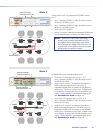
Ground (G)
Receive (Rx)
Transmit (Tx)
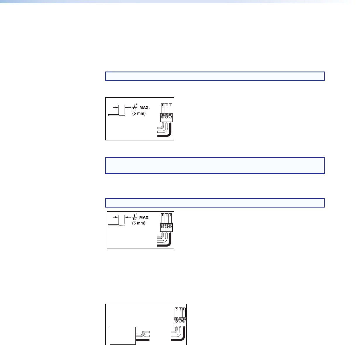
Bidirectional
RS-232
Device
Ground (G)
Receive (Rx)
Transmit (Tx)
RxTx G
Do not tin
the wires!
Figure 6. RS-232 Connector Wiring
c
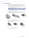
USB configuration port (front panel) — (see Front Panel Features on page11)
Female USB mini-B jack used for configuration of the switcher and firmware upgrades
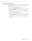
(see Updating Firmware on page48).
MPS601 • Installation 6