


SW2 DP • Installation 4
Rear Panel Features
12V
0.6A MAX
POWER
EDID
STORE
DEFAULT
21
STORED
RS-232 AUTO
Rx GTx
INPUTS OUTPUT EDID REMOTE
SW2 DP
3
2
1
6
7
5
4
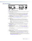
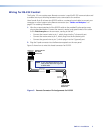
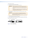
Figure 2. SW2 DisplayPort Rear Panel
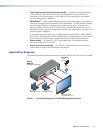
a Power connector — Plug the provided external 12 VDC power supply into this 2-pole,
3.5 mm captive screw connector.
b Input connectors — Connect DisplayPort input devices to these female DisplayPort
connectors. Equalizers on the inputs compensate for a poor source signal and allow
cable runs of up to 25 feet (7.6 m). Mini DisplayPort devices are supported with
the appropriate adaptors and cables (not provided). See “Wiring the DisplayPort
Connectors” on page 8 for the connector pin assignments.
c Output connector — Connect a DisplayPort output device to this female DisplayPort
connector. See “Wiring the DisplayPort Connectors” for the connector pin
assignments.
d EDID Store LED — This tri-colored LED lights to indicate EDID storing status:
• Red — EDID storing has been enabled (DIP switch 1 is set to Stored [down]) but
external EDID has not been stored and the factory default EDID is still present.
• Green — EDID storing has been enabled and the switcher is using external EDID.
• Amber — The EDID Store button has been pressed and the switcher is currently
storing EDID. (After the EDID is stored, the LED turns green.)
e EDID Store button — Press this recessed button (using a pointed stylus or a small
screwdriver) to store the EDID of the connected display device (see “Storing the
display EDID” on page 14).
f EDID DIP switch (switch 1, on the left) — Set this DIP switch to Stored (down) to
enable EDID storing. This is the default position (see “Storing the display EDID” for
more information).
Set the switch to Default (up) to use the SW DP2 default EDID of 1920x1080 @ 60 Hz
with 2-channel audio.
DIP switch 2 (on the right) is not used.
g Remote connector — This 5-pole, 3.5 mm captive screw connector can be used for
RS-232 communication with the switcher and to enable auto-input switching.
• For RS-232 control, connect the Tx (transmit), Rx (receive) and G (ground) pins to
your computer serial port (see “Wiring for RS-232 Control” on the next page).
• To enable auto-input switching, short pins 4 and 5 of this connector together. In
auto-input switch mode, the switcher automatically switches to the active input (see
“Enabling Auto-input Switching” on page 8).