


153
CHAPTER 7 8-BIT PWM TIMER
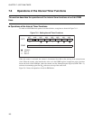
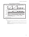
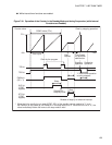
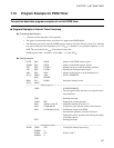
● While interval timer functions are enabled:
Figure 7.8-1 Operation of the Counter in the Standby Mode and during Suspension (while Interval
Functions are Enabled)
00
H
Counter value
FF
H
COMR value (FF
H
)
Clear by stopping operation
Timer cycle
Stop
request
Time to wait
for oscillation
stabilization
Time
Clear by the program
Stopping
operation
Restarting
operation
TIR bit
TPE bit
PWM pin
(OE = 1)
*
"L" level while operation
is being stopped
SLP bit
(STBC
register)
Sleep
Release of
sleep by IRQ9
Stop
STP bit
(STBC
register)
Release of stop by an external interrupt
When the bit to specify the pin state (STBC: SPL) of the standby control register is "1", and
the PWM pin is not pulled up, the PWM pin in the stop mode is Hi-Z. When the SPL bit is "0", the
va
lue immediately before the move to the stop mode is held.
*: